Liquid cooling permanent magnet speed inhibitor capable of stage division

A retarder and graded technology, applied in the field of gradeable liquid-cooled permanent magnet retarders, can solve the problems of increased rotor drum temperature, poor heat dissipation effect, low working reliability, etc., and achieves small volume and mass, overall Compact structure, good heat dissipation effect

Inactive Publication Date: 2009-02-04
BEIJING UNIV OF TECH
View PDF1 Cites 15 Cited by
  • Summary
  • Abstract
  • Description
  • Claims
  • Application Information

AI Technical Summary

Problems solved by technology

The permanent magnet retarder only has two working states of braking or non-braking, so the driver cannot provide the required braking torque according to the road conditions and vehicle speed, that is, the hierarchical control of the permanent magnet retarder cannot be realized
[0005] The invention patent (Patent No. ZL200510037966.3) titled "A Classified Control Permanent Magnet Retarder" discloses a permanent magnet retarder that can provide graded braking torque, but this permanent magnet The stator of the retarder is a bracket equipped with permanent magnets. Th...

Method used


Image

  • Liquid cooling permanent magnet speed inhibitor capable of stage division

Examples


Embodiment Construction

[0013] The present invention will be further described below in conjunction with accompanying drawing.

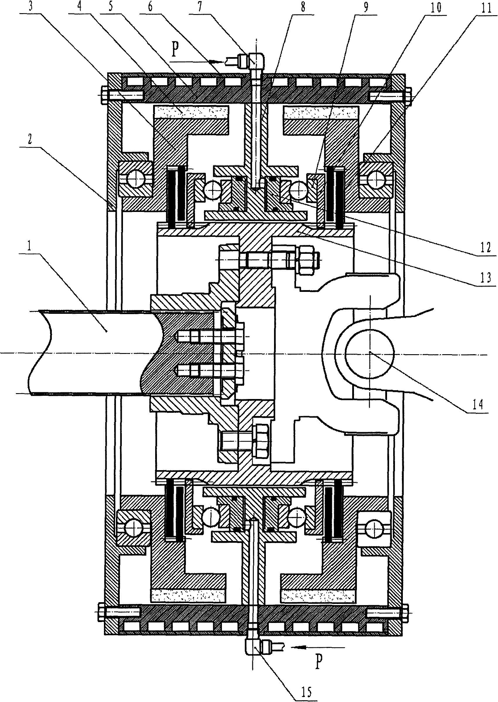
[0014] The specific structure of this embodiment is as figure 1 As shown, it includes a stator, a rotor, a control mechanism, a transmission output shaft 1 and a transition flange 13 fixedly connected to the transmission output shaft. The transition flange 13 is connected to the transmission shaft by bolts to provide a power source for the retarder.

[0015] The stator includes two bearing end caps 2 and a circular stator drum 5. The two bearing end caps 2 are respectively fixed on the two ends of the stator drum 5, forming a space with the stator drum 5, and the rotor and the control mechanism are placed in the space. inside the space. The bearing end cover 2 is fixedly connected with the stator drum 5 through bolts, and a channel for cooling water flow is provided on the outer surface of the stator drum 5 , and the channel is sealed by a water-cooling sealing cover 6 . ...


PUM


Abstract

The invention provides a gradable liquid cooling permanent-magnet retarder, and the retarder utilizes permanent magnets as eddy current brake magnetic sources, and carries out the auxiliary braking to an automobile vehicle through the reverse eddy current braking force produced by rotating non-contacting rotors or stators. The retarder comprises the stators, the rotors and a control mechanism. The stators include bearing end caps and stator drums, the rotors comprise a plurality of permanent magnets and magnet cages, and the rotors are connected with the stators through two rolling bearings, so the rotors can be rotationally positioned in the stators. The control mechanism is positioned in the rotors for controlling the transmission connection of spacer flanges and the rotors. Two sets of rotors of the permanent-magnet retarder are positioned at both sides of the control mechanism, and can work independently, thereby realizing the gradable control to the permanent-magnet retarder; the permanent magnets and the magnet cages serve as rotors, and the outer parts thereof have no rotating part; the control mechanism is easy to realize the switching of braking state of the permanent-magnet retarder; the permanent-magnet retarder has no magnetic leakage moment when in non-braking; and the retarder has advantages of compact overall structure and small volume and light weight.

Description

technical field [0001] The invention is a graded liquid-cooled permanent magnet retarder. The retarder uses NdFeB permanent magnets as the eddy current braking magnetic source, and the reverse eddy current braking force generated by rotating the non-contact rotor or stator, Auxiliary braking of vehicles. Background technique [0002] The retarder is a safety auxiliary device for driving brakes, which applies the braking force to the transmission parts of the vehicle to reduce the driving speed of the vehicle. At present, the retarders commonly used at home and abroad mainly include hydraulic retarders and electric eddy current retarders. Although their working principles are different, as an auxiliary braking device, their effects are obvious. The permanent magnet type retarder uses its own permanent magnet to form a magnetic field to play a retarding role, so there is almost no power consumption. [0003] The biggest features of the permanent magnet retarder are: 1. It ca...

Claims


Application Information

Patent Timeline
IPC IPC(8): H02K49/04
Inventor 李德胜叶乐志马元京王文武
Owner BEIJING UNIV OF TECH
Why Eureka
Try Eureka