Clamping head of blanking machine

A blanking machine and machine clip technology, which is applied to the accessories of tool clips, turning equipment, automatic/semi-automatic lathes, etc., can solve the problems affecting the machining accuracy of the workpiece, achieve the effect of novel structure and ensure dimensional consistency

Inactive Publication Date: 2009-02-11
钟树平
View PDF0 Cites 8 Cited by
  • Summary
  • Abstract
  • Description
  • Claims
  • Application Information

AI Technical Summary

Problems solved by technology

However, with this structure, the friction between the workpiece and the collet will cause relative rotation or axial movement between the collet and the workpiece, which will affect the machining accuracy of the workpiece.

Method used


Image

  • Clamping head of blanking machine
  • Clamping head of blanking machine
  • Clamping head of blanking machine

Examples


Embodiment Construction

[0015] Below in conjunction with accompanying drawing and specific embodiment the present invention is described in further detail:

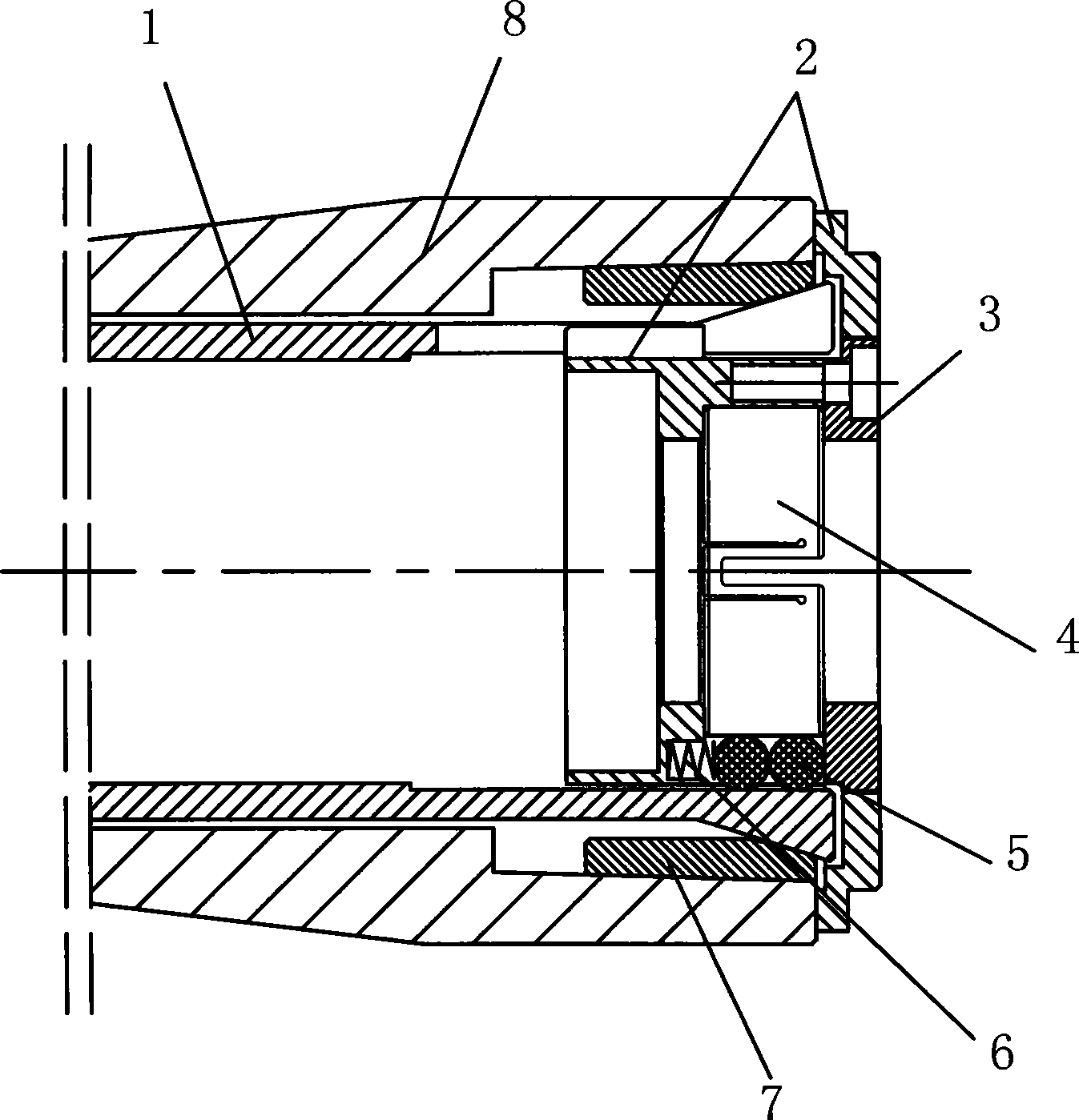
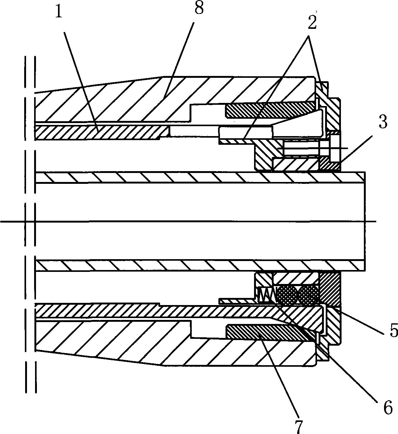
[0016] See Figure 1 ~ Figure 3 , The chuck of the blanking machine is mainly composed of a spring chuck 1, a movable component 5, a clamping sleeve 4, and the like.

[0017] The outer side of the left end of the collet 1 is provided with a taper, the taper is provided with an outer locking sleeve 7, the outer locking sleeve 7 is installed on the main shaft 8, and the inner side of the collet 1 is provided with a clamping sleeve 2, One end of the clamping sleeve 2 protrudes from the collet 1 .

[0018] The clamping sleeve 2 is provided with a plurality of rolling grooves, the elastic component and the movable component 5 are movably arranged in the rolling grooves, and the inner side of the movable component 5 is provided with a clamping sleeve 4 .

[0019] Preferably, the tightening sleeve 4 is provided with long grooves in opposite direction...


PUM


Abstract

The invention discloses a chuck of a blanking machine, and the structure of the chuck consists of a spring chuck, a movable component, and a clamping sleeve; taper is arranged at the outer side of the left end of the spring chuck and is provided with an external locking sleeve which is installed on a main axle; a clamping sleeve carrier is arranged at the inner side of the spring chuck; one end of the clamping sleeve carrier extends out of the spring chuck; a plurality of rolling chutes are arranged on the clamping sleeve carrier; an elastic component and the movable component are movably arranged in the rolling chute; the clamping sleeve is arranged at the inner side of the movable component; by the arrangement of the movable component, axial play produced by the fraction force of the chuck can be transformed into the rolling force of a rolling component; that is, the clamping sleeve only receives compaction force transmitted by the rolling component; the compaction force clamps the workpiece, without producing the axial play, thus guaranteeing the consistency of the size of cutting workpiece.

Description

technical field [0001] The invention relates to a blanking machine, in particular to a chuck of a blanking machine. Background technique [0002] At present, the spring collet commonly used on the machine tool for positioning and clamping the workpiece is to connect and tighten the external thread of the pull rod with the rear end internal thread of the collet to generate axial tension. The collet is compressed by the tapered surface at the front end of the machine tool spindle, converting the axial pulling force into a clamping force perpendicular to the center of the collet, thereby clamping the workpiece. However, with this structure, the friction between the workpiece and the collet will cause relative rotation or axial movement between the collet and the workpiece, which will affect the machining accuracy of the workpiece. Contents of the invention [0003] Aiming at the deficiencies in the prior art, the invention provides a chuck of a blanking machine with a novel ...

Claims


Application Information

Patent Timeline
Patent Type & Authority Applications(China)
IPC IPC(8): B23B13/12B23B31/10
Inventor 戴秀年
Owner 钟树平
Why Eureka
Try Eureka