Electric sliding rail lifting assembly for car seat

A technology of car seats and slide rails, applied in the field of vehicle parts, can solve the problems of difficult control of assembly accuracy, complex processing technology, and limited versatility, and achieve simple and stable procedures, simple processing technology, and ensure dimensional stability and consistency sexual effect

Inactive Publication Date: 2012-10-03
常州华阳万联汽车附件有限公司
View PDF11 Cites 1 Cited by
  • Summary
  • Abstract
  • Description
  • Claims
  • Application Information

AI Technical Summary

Problems solved by technology

[0003] At present, the seats on the market mainly realize the front and rear, height adjustment through the slide rail and the lifting part, and the structure is complicated, which makes it difficult to control the assembly accuracy.
In addition, most of the core parts in the slide rail are made of sheet metal, and the processing technology is complicated, which limits the versatility of the structure in terms of material selection and processing technology. If the stroke or installation size required by the car seat is different or changed, the It can't be used anymore. If you borrow it, you can only re-open the mold to realize it, which is time-consuming and laborious

Method used


Image

  • Electric sliding rail lifting assembly for car seat
  • Electric sliding rail lifting assembly for car seat
  • Electric sliding rail lifting assembly for car seat

Examples


Embodiment Construction

[0023] The preferred embodiments of the present invention will be described in detail below in conjunction with the accompanying drawings, so that the advantages and features of the present invention can be more easily understood by those skilled in the art, so as to define the protection scope of the present invention more clearly.

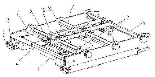
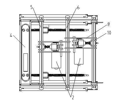
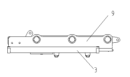
[0024] see Figure 1 to Figure 3 , the embodiment of the present invention includes:

[0025] An electric slide rail lifting assembly for a car seat, comprising: a left slide rail assembly, a right slide rail assembly, a horizontal motor 1 and two lifting motors 2, and both the left slide rail assembly and the right slide rail assembly include a slide case 3 And a sliding core 9 that can slide in the sliding case 3, a beam 4, a fixed rod 6 and two lifting transmission rods 5 are arranged between the sliding core 9 of the left slide rail assembly and the sliding core 9 of the right slide rail assembly, The horizontal motor 1 is fixedly connected ...


PUM


Abstract

The invention discloses an electric sliding rail lifting assembly for a car seat. The electric sliding rail lifting assembly comprises a left sliding rail assembly, a right sliding rail assembly, a horizontal motor and two lifting motors, wherein both the left sliding rail assembly and the right sliding rail assembly comprise sliding housings and sliding cores capable of sliding in the sliding housings; a beam, a fixing rod and two lifting drive rods are arranged between the sliding core of the left sliding rail assembly and the sliding core of the right sliding rail assembly; the horizontal motor is fixedly connected with the sliding cores through the beam and the output end of the horizontal motor is fixedly connected with the sliding housings; the tail part of the lifting motor is fixed to a lifting motor fixing sheet and the output end of the lifting motor is fixedly connected with the lifting drive rods through a connecting sheet; the two ends of each of the lifting drive rods are fixedly connected with lifting output connecting sheets; and the sliding housings and the sliding cores are all formed by making sliding housing sections and sliding core sections according to the design structures in advance and then punching corresponding holes on the sliding housing sections and the sliding core sections. Therefore, the electric sliding rail lifting assembly has the advantages of compact and simple structure, light weight, good stability and strong commonality.

Description

technical field [0001] The invention relates to the field of vehicle parts, in particular to an electric slide rail lifting assembly for a car seat. Background technique [0002] In our country, the automobile industry is developing rapidly, and the automobile slide rail industry is produced along with the automobile industry. The slide rail is one of the main functional parts of the automobile seat. Existing car seats, especially driver's seats, are required to have flexible front and rear adjustment and up and down adjustment capabilities, so as to better meet the requirements of different drivers for seat positions. The realization of the car seat front and rear, up and down adjustment mainly relies on the slide rail under the seat to realize. [0003] At present, the seats on the market mainly realize front and rear, height adjustment through two parts of slide rail and lifting, and the structure is complicated, which makes it difficult to control the assembly accuracy....

Claims


Application Information

Patent Timeline
Patent Type & Authority Applications(China)
IPC IPC(8): B60N2/07B60N2/16
Inventor 岳逸阳
Owner 常州华阳万联汽车附件有限公司
Why Eureka
Try Eureka