Web adhesive foot for wind turbine blade, wind turbine blade and forming method thereof

A wind power blade and molding method technology, applied in the field of web bonding feet, can solve problems such as difficult control of bonding structural adhesives, and achieve the effects of ensuring dimensional consistency, versatility, and process simplicity

Inactive Publication Date: 2019-05-31
SHANGHAI ELECTRIC WIND POWER GRP CO LTD
View PDF4 Cites 2 Cited by
  • Summary
  • Abstract
  • Description
  • Claims
  • Application Information

AI Technical Summary

Problems solved by technology

In addition, the bonding width of blades is getting larger and larger, and the control of bonding structural adhesives is becoming more and more difficult.

Method used


Image

  • Web adhesive foot for wind turbine blade, wind turbine blade and forming method thereof
  • Web adhesive foot for wind turbine blade, wind turbine blade and forming method thereof
  • Web adhesive foot for wind turbine blade, wind turbine blade and forming method thereof

Examples


Embodiment 1

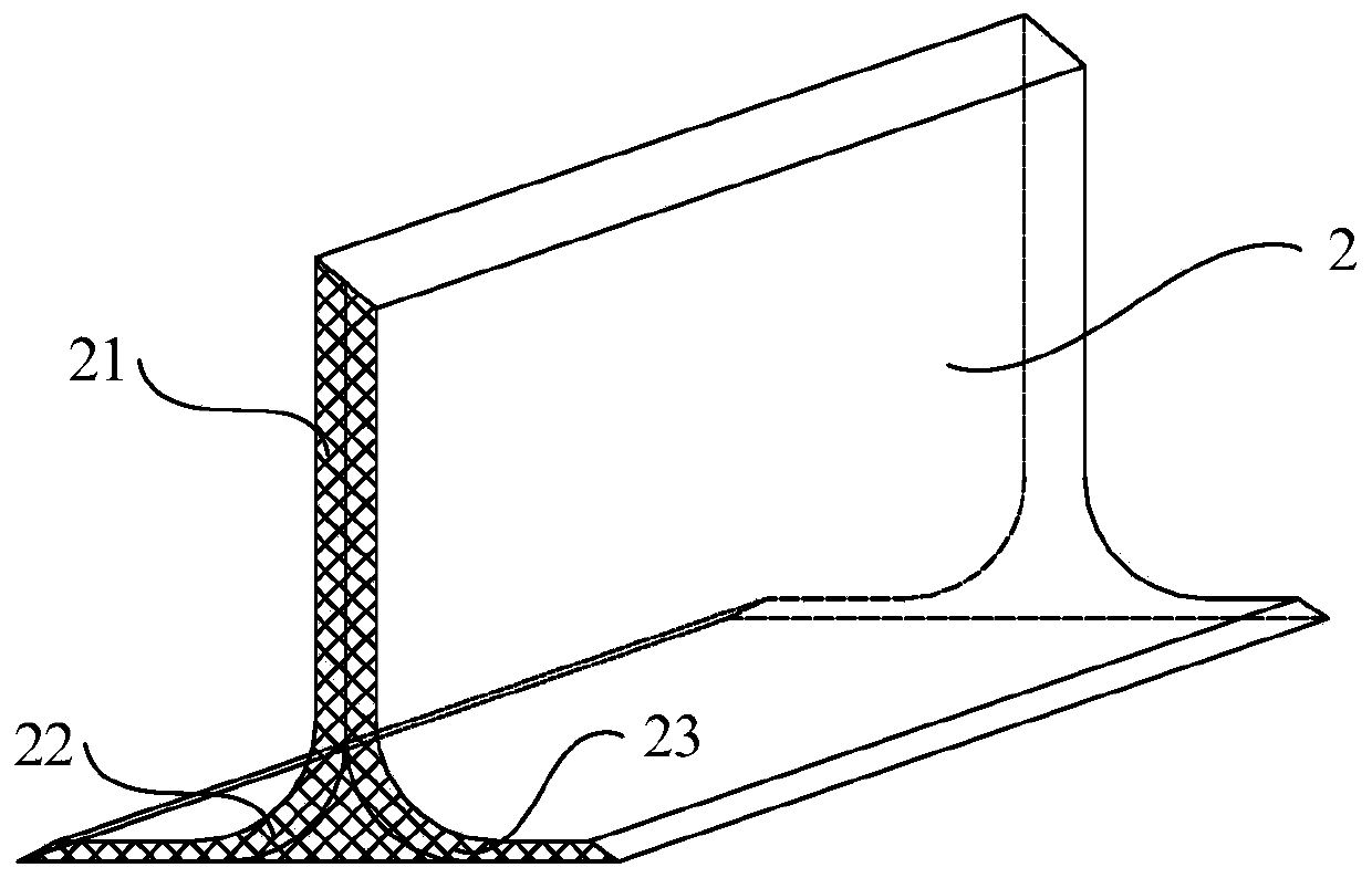
[0044] Such as image 3 As shown, the longitudinal section of the web bonding foot 2 of the present invention is an inverted "T" shape, including a main body 21 and an outer extension 22 and an inner extension 23 connected to the main body 21 .

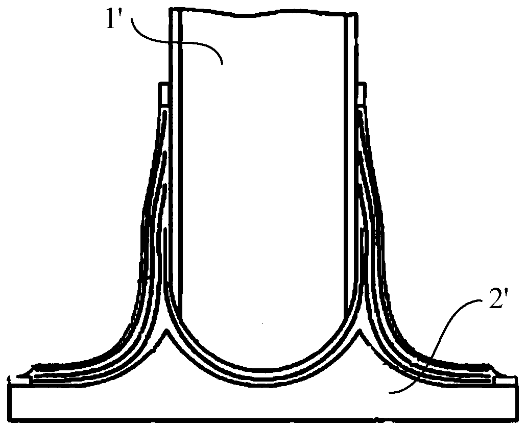
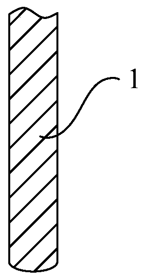
[0045] Such as Figure 2-Figure 4 As shown, the present invention provides a wind power blade, which includes a web plate structure 1, and also includes two web bonding feet 2 connected to the web plate structure 1, and the web plate structure 1 is inserted into the two web bonding feet 2; wherein the longitudinal section of each web bonding foot 2 is an inverted "T" shape, including a main body 21 and an outer extension 22 and an inner extension 23 connected with the main body 21 .

[0046] The invention provides a method for forming a wind power blade, which specifically includes the following steps:

[0047] S1, making the web plate structure 1 through the web mold;

[0048] S2, making the web bonding foot 2, making the web bond...

Embodiment 2

[0055] Such as Figure 5 , Figure 6As shown, the steps of this embodiment are basically the same as those of Embodiment 1, the difference being that step S4 is the following steps: Insert the web plate 1 between the two web bonding feet 2, and glue the two webs together The connecting pin 2 and the web plate structure 1 are poured with resin 5 to form the whole web, lay the web plate structure 1 flat, and lay 2- Three layers of glass fiber cloth 6, two web bonding feet 2 are laid, and clamping tools 7 are used at intervals in the length direction of the web plate structure 1, so that the web bonding feet 2 and the web plate structure 1 are fixed, Vacuumize the laying vacuum system, pour the resin 5 between the web bonding foot 2 and the web plate structure 1 through vacuum infusion, and heat and cure; step S5 is the following steps: pass the whole web and the main shell 3 through the structure Glue 4 bonding, forms blade. As an alternative, other adhesives can also be used...


PUM


Abstract

The invention discloses a web adhesive foot for a wind turbine blade, the wind turbine blade and a forming method thereof. The longitudinal section of the web adhesive foot is in an inverted-T shape and comprises a main body, an external extending part and an internal extending part, and the external extending part and the internal extending part are connected with the main body. The forming method of the wind turbine blade comprises the following steps that a web slab structure is manufactured through a web mold; web adhesive feet are manufactured, are in the inverted-T shape, and each comprises the main body, the external extending part and the internal extending part, and the external extending part and the internal extending part are connected with the main body; the two web adhesive feet are used and oppositely placed, and the distance between the web adhesive feet is adjusted according to the thickness of a web slab. Through the forming method of the wind turbine blade, the sizeconsistency of the web adhesive feet can be ensured, and the technology diversity is provided.

Description

technical field [0001] The invention relates to a web bonding foot of a wind power blade, a wind power blade and a forming method thereof. Background technique [0002] With the rapid development of the wind power industry, the length and type of blades are increasing, and the competition is becoming increasingly fierce. The requirements for cost control and reliability of wind power are getting higher and higher. As the main component, the blade has a great influence on the cost and reliability of the wind turbine. [0003] At present, there are more and more situations where multiple types of blades share a pair of main molds. However, due to the different thicknesses of the main beams of different types of blades, it is difficult to use common web molds, and the molds need to be adjusted many times during production. Such as figure 1 As shown, the web plate structure 1' and the web bonding foot 2' must be integrally poured and solidified before being bonded together wi...

Claims


Application Information

Patent Timeline
Patent Type & Authority Applications(China)
IPC IPC(8): B29C70/44B29C70/54B29C70/84F03D80/00B29L31/08
CPCY02E10/72Y02P70/50
Inventor 文欢刘培文齐志攀
Owner SHANGHAI ELECTRIC WIND POWER GRP CO LTD
Why Eureka
Try Eureka