Testing device for implementing main torque and vibrating torque to high speed rotary main shaft

A test device and spindle technology, applied in the direction of mechanical bearing testing, etc., can solve the problems of not being able to simulate high-speed rotating spindles at the same time, the structure of the test device being complex, and the inability to compound loading, etc., and achieve the effects of simple structure, easy manufacturing and low manufacturing cost.

Active Publication Date: 2009-02-18
CHENGDU ENGINE GROUP
View PDF0 Cites 16 Cited by
  • Summary
  • Abstract
  • Description
  • Claims
  • Application Information

AI Technical Summary

Problems solved by technology

[0004] The present invention provides a test device that can simultaneously implement main torque and vibration torque loads on a high-speed rotary spindle in view of the shortcomings of the existing high-speed rotary spindle strength test device, and aims to solve the problem that the prior art test device cannot be well and effectively The problem of compound loading of the main torque and vibration torque on the high-speed rotary spindle cannot be well and effectively simulated at the same time the main torque load and the vibration torque load on the high-speed rotary spindle during operation. Problems such as high cost and high failure rate

Method used


Image

  • Testing device for implementing main torque and vibrating torque to high speed rotary main shaft
  • Testing device for implementing main torque and vibrating torque to high speed rotary main shaft
  • Testing device for implementing main torque and vibrating torque to high speed rotary main shaft

Examples


Embodiment 1

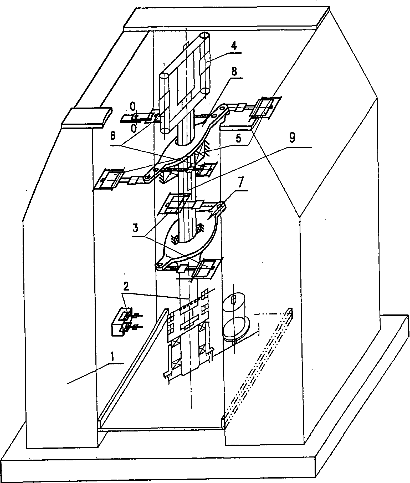
[0030] This embodiment provides a test device capable of implementing main torque and vibration torque on a high-speed rotating spindle, and its structure is as attached figure 1 As shown in the figure, by the device frame 1, the main torsion arm 7, the anti-torsion arm 9, the force constitutes the main torsion couple of 2 main torsion actuator mechanisms 4, and the force constitutes the vibration torsion couple of 2 vibration actuators The mechanism 5 is composed of two spring anti-twist actuating mechanisms 6 whose reaction force constitutes a anti-torque couple, and a hydraulic servo system that controls four actuating cylinder mechanisms by four electromagnetic hydraulic servo valves respectively. The two main torsion actuator mechanisms, the two vibration actuator mechanisms and the two spring anti-twist actuator mechanisms are all arranged symmetrically. The device frame 1 is a gantry structure, consisting of a base, two wall columns and beams. The main torsion arm 7 and th...

Embodiment 2

[0032] This embodiment provides a test device capable of implementing main torque and vibration torque on a high-speed rotating spindle. The structure is as attached figure 1 And figure 2 As shown, its structure is basically the same as that of embodiment 1, the difference is that on the basis of embodiment 1, a bending moment loading mechanism 2 and an axial force loading mechanism 10 are added to the test device. The bending moment loading mechanism passes a bending moment loading shaft 3 Connected with the rotating shaft test piece, the axial force loading mechanism directly acts on the rotating shaft test piece. The other structure is the same as that of Example 1. The test device of this embodiment can not only simulate the main torque load and high-frequency vibration load under the running state of the high-speed rotating spindle completely and truly, but also simulate the bending moment load and the axial load. Perform comprehensive tests under various loads.


PUM


Abstract

The invention discloses an intensity test device which enables the main torque and the vibration torque of a high-speed rotary spindle to be loaded; the test device mainly structurally comprises a device rack, a main torsion beam and a reverse torsion beam which are fixedly connected with the rotary spindle arranged on the rack, at least a pair of main torsional actuating cylinder mechanisms with the bearing end fixed on the device rack and the action force of the mobile end twisted with the torsion beams forming the main torsional couple, at least a pair of vibration actuating cylinder mechanisms with the action force forming the vibration torsional couple, at least a pair of elastic reverse torsional actuating mechanisms with the reverse action force forming the reverse torsional couple, as well as a hydraulic servo system which controls the movement of the actuating cylinder mechanisms. The invention breaks through the torque load mode of the high-speed rotary spindle test device in the prior art and can completely and really simulate the main torque and vibration torque load borne by the high-speed rotary spindle during the running process so as to solve the problem of difficult composite load of the main torque and the vibration torque. The invention also has the advantages of high load accuracy, low manufacturing cost, small maintenance workload and long service life.

Description

Technical field [0001] The invention relates to a strength test device for a high-speed rotating main shaft, in particular to a strength test device capable of simultaneously implementing a main torque and a vibration torque load on the high-speed rotating main shaft to determine the life of the rotating shaft. Background technique [0002] The rotating main shaft of high-speed rotating machinery such as turbine engines and steam turbines is the most important component of this type of machinery, which bears a large variety of loads during operation. image 3 As shown, it is necessary to withstand loads such as bending moment Mu, main torque Mk, vibration torque △Mk, axial force P, and because there are many stress-concentrated parts such as steps and holes that are prone to cracks, once cracks occur during operation It may cause fatal consequences of broken shafts, causing serious accidents such as personal injury and death and major property losses. Because the gyroscopic momen...

Claims


Application Information

Patent Timeline
Patent Type & Authority Applications(China)
IPC IPC(8): G01M13/04
Inventor 刘建王春笋苟华忠郑树桐周军
Owner CHENGDU ENGINE GROUP
Why Eureka
Try Eureka