Dynamic real-time monitoring method for concrete bridge prestressed tendon tensioning force and special prestress construction system

A prestressed tendon, real-time monitoring technology, applied in bridges, bridge materials, bridge construction, etc., can solve problems such as abnormal correspondence, collapse of beam ends, and inability to calculate by itself

Active Publication Date: 2016-05-25
CHINA RAILWAYS CORPORATION +3
View PDF7 Cites 21 Cited by
  • Summary
  • Abstract
  • Description
  • Claims
  • Application Information

AI Technical Summary

Problems solved by technology

However, the previous construction methods can only check the final tensioning results. If there is a misoperation or a large deviation in the tensioning force during the tensioning process, the steel strand will slip or break, and there will be a large deviation in the elongation value at this time. , can not be detected in time through the abnormal elongation value, which may cause serious construction or personnel safety accidents such as prestressed breakage, clamp ejection, beam end crushing, etc.
Therefore, the traditional construction technology is difficult to meet the dual control requirements of "focusing on stress control and elongation as a check".
[0007] At the same time, the main problems in the control mode and process of the previous "intelligent tensioning" equipment are as follows: First, the hardware uses the hydraulic pressure collected by a single sensor to replace the measured tension or collect the measured tension to reach the preset target value of the program. The only condition for the termination of the action is that the sensor has a single detection poin

Method used


Image

  • Dynamic real-time monitoring method for concrete bridge prestressed tendon tensioning force and special prestress construction system
  • Dynamic real-time monitoring method for concrete bridge prestressed tendon tensioning force and special prestress construction system
  • Dynamic real-time monitoring method for concrete bridge prestressed tendon tensioning force and special prestress construction system

Examples


Example Embodiment

[0166] The present invention will be further described below in conjunction with the embodiments, but it is not intended to limit the present invention. The scope of protection of the present invention shall be subject to the contents of the claims. Any substitution of equivalent technical means based on the specification shall not depart from the present invention. protected range.

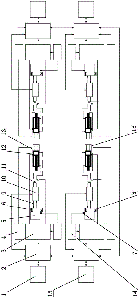
[0167] This embodiment consists of two sets of tensioning devices, namely A master and A slave and B master and B slave, which are divided into two groups and are respectively arranged at both ends of the tensioned beam. Such as figure 2 Shown. The structural composition, working principle and dynamic real-time monitoring method of the tension force of the prestressed tendons of the two sets of tensioning devices are completely the same. Now only one group of the A master and the B master is used as an example for illustration. Each tensioning device includes hydraulic station 5, reversing valve g...


PUM


Abstract

The invention belongs to bridge construction, and particularly relates to dynamic real-time monitoring method for concrete bridge prestressed tendon tensioning force and a special prestress construction system. The dynamic real-time monitoring method for the concrete bridge prestressed tendon tensioning force includes the steps of initializing and real-time dynamic control loading. The prestress construction system comprises at least one tensioning device, and each tensioning device comprises a hydraulic station, a reversing valve bank, a jack, an A/D data collecting module, a PLC, a central processing unit, a human-computer interface, a direct force measuring device, a hydraulic force measuring device, a prestressed tendon elongation measuring device, a friction resistance test device and a security alarm device. The double-control requirement, difficult to met in the prior art, for taking stress control as the principle thing and an elongation value as a checking item is met, the dynamic real-time monitoring method has the advantages that construction quality and safety can be effectively ensured, and problems found in the tensioning process can be solved in time.

Description

technical field [0001] The invention belongs to bridge construction, in particular to a dynamic and real-time monitoring method and a special prestressed construction system for the tension force of prestressed tendons of concrete bridges. Background technique [0002] In the construction of high-speed railways in my country, bridges occupy an absolute proportion in the length of the lines because of their good ride comfort, the line is not easy to settle, the land is saved, and the operation is safe. The prestressed concrete bridge has the characteristics of strong crack resistance, good impermeability, high rigidity, high strength, good shear resistance and fatigue resistance. Both cracking and deflection reduction are very effective, allowing bridge structures to be designed more economically, lightweight and aesthetically pleasing. [0003] With the application of prestressing technology in modern bridge construction, the quality and performance of bridges have been gre...

Claims


Application Information

Patent Timeline
IPC IPC(8): E01D21/00E04G21/12G01L5/00E01D101/28
CPCE01D21/00E01D2101/28E04G21/121G01L5/0033
Inventor 肖祥淋马林牛斌苏永华朱希同杨心怡叶剑波刘凯辉吴鑫
Owner CHINA RAILWAYS CORPORATION
Why Eureka
Try Eureka