
Output circuit of parallel connection power supply

A technology of power output and parallel connection, applied in circuit devices, emergency power supply arrangements, emergency protection circuit devices, etc., can solve the problems of low power output, load power failure, circuit reliability problems, etc., and achieve the effect of improving reliability.

Inactive Publication Date: 2009-02-18
LIEBERT
View PDF0 Cites 0 Cited by
  • Summary
  • Abstract
  • Description
  • Claims
  • Application Information

AI Technical Summary

Problems solved by technology

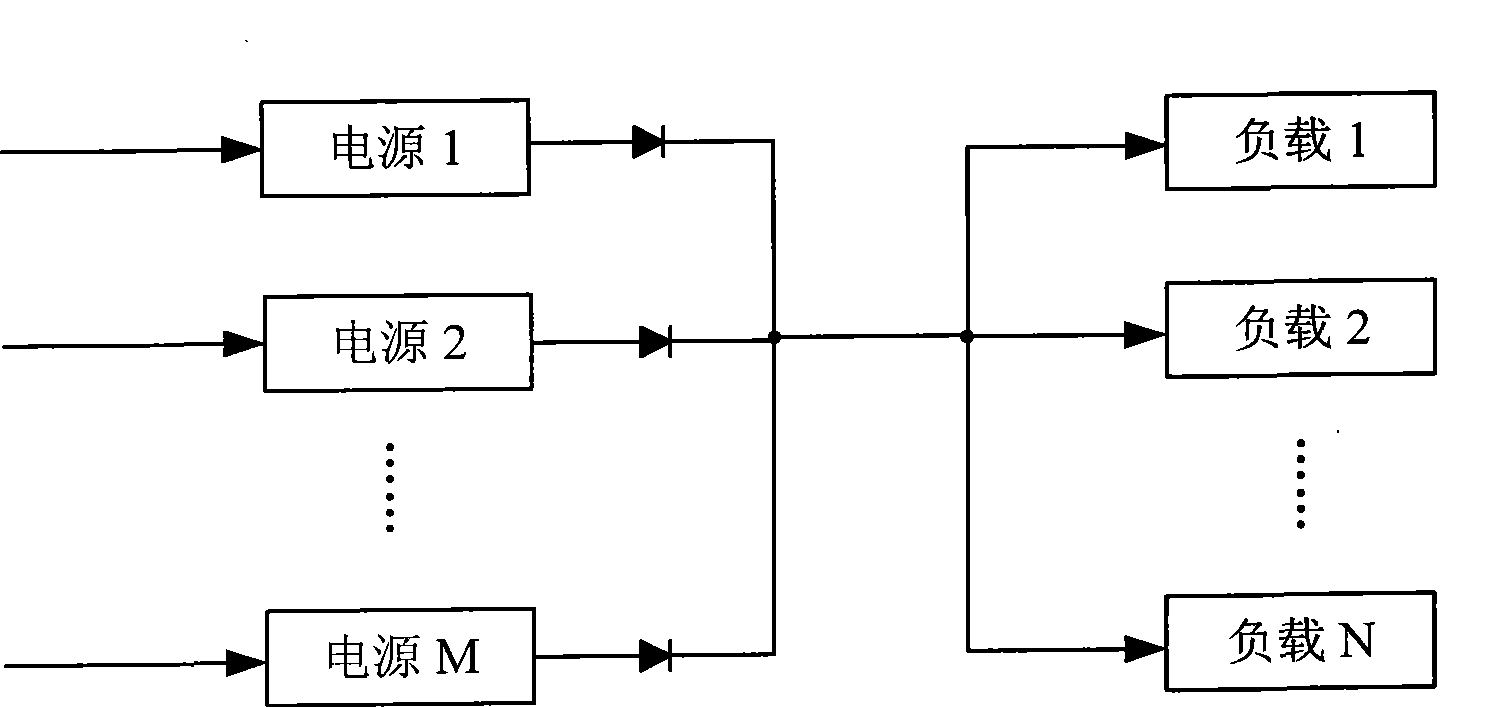
This kind of circuit has great disadvantages: when a load fails, such as a short circuit, all power supply outputs will be pulled down, causing all loads to lose power, and the circuit reliability is not high
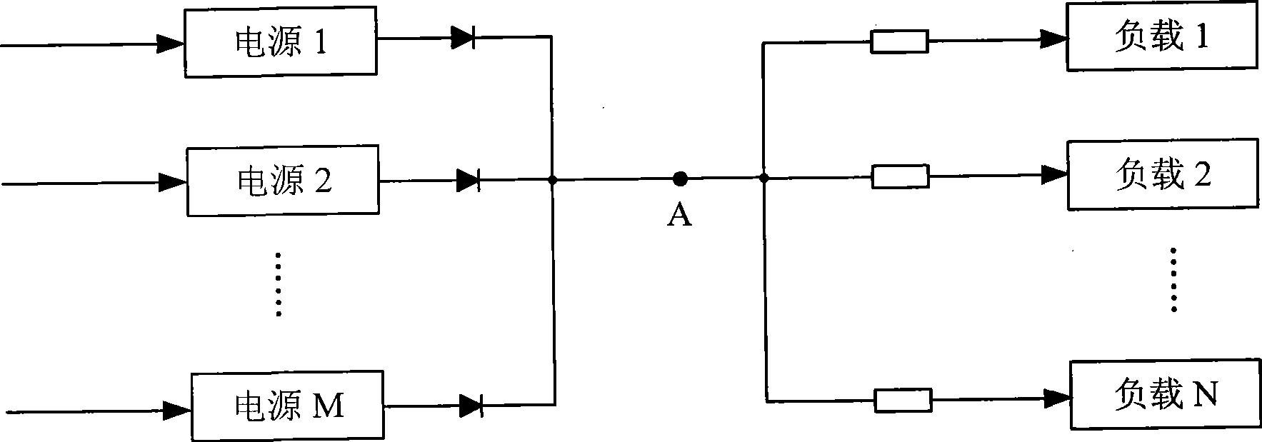
but figure 2 The circuit still has reliability problems, for example: when a fault occurs at a certain point on the output bus, it will still cause all loads to be powered down

Method used


Image

  • Output circuit of parallel connection power supply
  • Output circuit of parallel connection power supply
  • Output circuit of parallel connection power supply

Examples


specific Embodiment approach 1

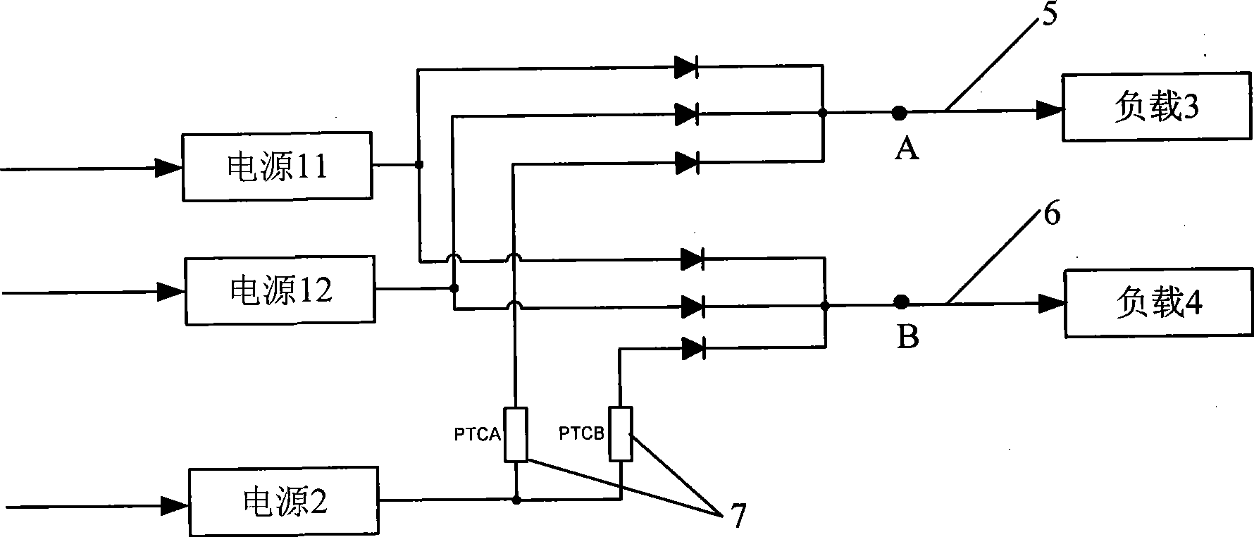
[0017] like image 3 As shown, a parallel power supply output circuit includes a power supply 11 , a power supply 12 , a power supply 2 , a load 3 , and a load 4 connected in parallel. The parallel connected power supply 11 , power supply 12 , and power supply 2 are connected to the load 3 through the output bus 5 , and connected to the load 4 through the output bus 6 . The parallel power supplies are divided into two groups, wherein, the power supply 11 and the power supply 12 are used as the main power supply, and the power supply 2 is used as the backup power supply. The meaning of backup here does not mean that the backup power supply does not work when the circuit is working normally, but is only used to distinguish the working conditions of each power supply in the parallel power supply when a fault occurs. A first protection circuit 7 is connected in series between the power supply 2 and the output bus 5 , and a first protection circuit 7 is also connected in series be...

specific Embodiment approach 2

[0019] The difference between this specific embodiment and the first specific embodiment is that: there are multiple backup power sources, and there are multiple loads on each output bus. like Figure 4 The parallel power supply output circuit shown includes power supply 11,..., power supply 1K, power supply 21,..., power supply 2N and load 1,..., load M in parallel . Each power supply is connected to the load through the output bus, the power supply 11, . . . , power supply 1K is used as the main power supply, and the power supply 21, . A first protection circuit is respectively connected in series between the backup power supply and each output bus, which are thermistors PTCA and PTCB in this specific embodiment, and the loads connected to each output bus are load groups comprising at least two loads, such as Figure 5 As shown, load 1 is a load group including load 11, load 12, ..., load 1L. Obviously, other loads, such as load M, can also be a load group including two or...


PUM


Abstract

The invention discloses a parallel connection power supply output circuit, for outputting parallel connection power supply to at least two loads through output buses, wherein the output buses having at least two which being connected with the loads separately, and the parallel connection power supply containing a main power source and a backup power source, and a first protective circuit being jointed up in-series between the backup power source and at least one output bus. The invention joints up the first protective circuit in series, so as to avoid power-down of the whole system due to either single point fault and improves the reliability of the parallel connection power supply output circuit greatly.

Description

technical field [0001] The invention relates to a parallel power supply output circuit. Background technique [0002] In order to improve reliability and load capacity, multiple power supplies are now connected in parallel to supply power to multiple loads. like figure 1 As shown, M power supplies are connected in parallel to N loads through the output bus to supply power to these loads. This kind of circuit has a big disadvantage: when a load fails, such as a short circuit, all power outputs will be pulled down, causing all loads to lose power, and the reliability of the circuit is not high. In order to increase the reliability of the circuit, such as figure 2 As shown, a protection circuit is added in front of each load, so that when a load fails, the protection circuit operates, and other loads are not affected. but figure 2 There are still reliability issues in the circuit, for example: when a fault occurs at a certain point on the output bus, it will still cause ...

Claims


Application Information

Patent Timeline
Patent Type & Authority Applications(China)
IPC IPC(8): H02J9/00H02H7/22
Inventor 刘玉伟刘兆燊徐福斌彭怀东
Owner LIEBERT
Learn More