Spare power automatic switching device and method for three-segment bus two-segment switch

A technology of bus section and backup auto-initialization, which is applied in the direction of circuit devices, electrical components, emergency power supply arrangement, etc., can solve the problems of lower reliability and complex auto-initialization logic, and achieve the effect of preventing malfunction or refusal to operate

Inactive Publication Date: 2009-02-18
BAOWU CHARCOAL MATERIAL TECH CO LTD
View PDF3 Cites 44 Cited by
  • Summary
  • Abstract
  • Description
  • Claims
  • Application Information

AI Technical Summary

Problems solved by technology

The design of the backup auto-switching device should avoid seeking perfection. Any device that unrealistically seeks to adapt to all fault situations or even imagined rare fault situations will greatly reduce the reliability due to the overly complicated auto-switching logic.

Method used


Image

  • Spare power automatic switching device and method for three-segment bus two-segment switch
  • Spare power automatic switching device and method for three-segment bus two-segment switch
  • Spare power automatic switching device and method for three-segment bus two-segment switch

Examples


Embodiment 1

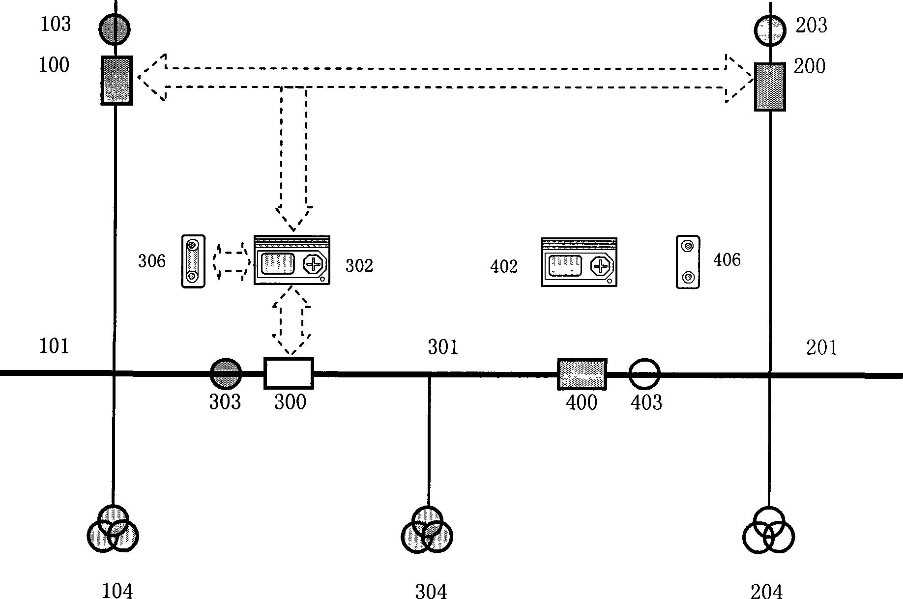
[0130] Operation mode: the first incoming circuit breaker 100 supplies power to the first bus section 101 alone, and the second incoming circuit breaker 200 supplies power to the second and third bus sections 201 and 301 at the same time (such as image 3 shown).

[0131] Its first section circuit breaker is in the "hot standby" position and its second section circuit breaker is in the "running" position.

[0132] The first and second backup power automatic input controllers respectively adopt the following methods: Figure 5 , Image 6 The wiring method; and adopt Figure 7 , 8 The logical relationship shown.

[0133] Put the first throwing / retracting plate 306 on, and take off the second throwing / retracting plate 406.

[0134] When a no-current or no-voltage fault occurs in the second bus section 201, the first start-up condition judging circuit of the first standby power supply controller 302 is started, and the second incoming circuit breaker 200 is judged to be not o...

Embodiment 2

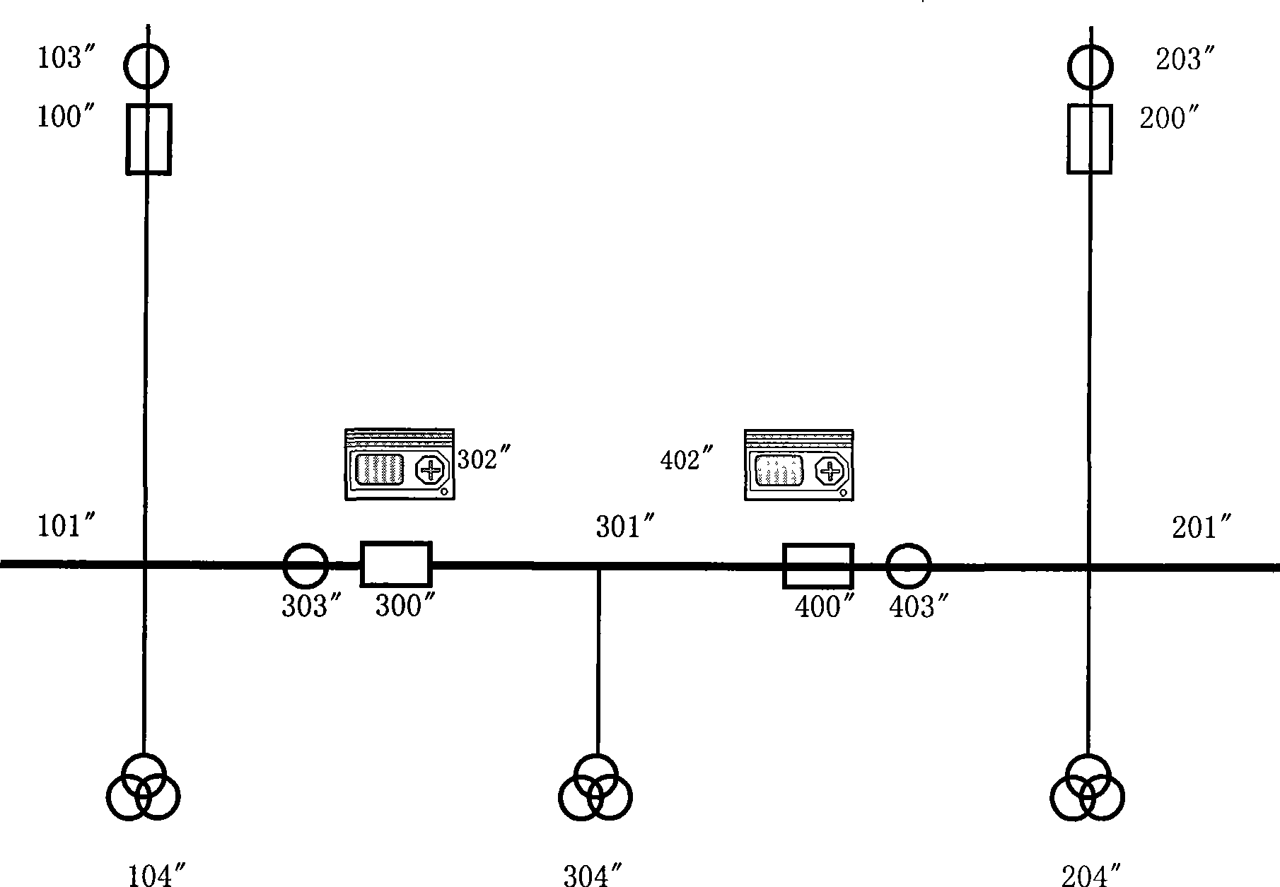
[0139] Operation mode: the first incoming circuit breaker 100 supplies power to the first and third bus sections 101 and 301 at the same time, and the second incoming circuit breaker 200 supplies power to the second bus section 201 alone (such as Figure 4 shown).

[0140] Its first section circuit breaker is in the "RUN" position and its second section circuit breaker is in the "Hot Standby" position.

[0141] The first and second backup power automatic input controllers respectively adopt the following methods: Figure 5 , Image 6 The wiring method; and adopt Figure 7 , 8 The logical relationship shown.

[0142] The first throwing / retracting plate 306 is taken off, and the second throwing / retracting plate 406 is put on.

[0143] When a no-current or no-voltage fault occurs in the second bus section 201, the first start-up condition judging circuit of the second backup power supply is automatically put into the controller 402 to start, after judging that the second inc...


PUM


Abstract

A three-busbar two-section switch standby self-casting apparatus, belonging to power distribution field, includes two power supply lead-in circuit breakers, three busbar segments and two section breakers. Two standby self-casting devices being mounted on the position of the two section breakers; the standby self-casting device being equipped with a current detection loop, a voltage detection loop and a control circuit; the current detection loop using the signal of a two-path lead-in current transformer as ''non stream'' criterion, and using the current signal of the corresponding section breaker as ''over current'' criterion; while the voltage detection loop using the voltage signals of the two busbar segments, neighboring the corresponding section breaker, as ''pressure/non-pressure'' criterion. The standby power supply self-casting device includes a electrification discrimination circuit, a first and a second startup condition judgment circuit, a standby self-casting motion circuit and a rear acceleration motion circuit. The invention also discloses standby self-casting method for the apparatus. The apparatus implements power supply rapid automatic switching when the lead-in is failure under different running modes of the three-section busbar, and ensures the power supply reliability under accidents status.

Description

technical field [0001] The invention belongs to the field of control devices or systems for power supply and distribution, and in particular relates to a switching-on / off device for emergency or standby power. Background technique [0002] Backup self-injection device, that is, the backup power automatic input device (or called the backup power automatic input device), is an automatic device installed in the power system to improve the reliability of power supply. Continuous power supply plays an important role. Its function is to quickly disconnect the working power supply and put the standby power supply into operation when the working power supply disappears due to failure or other reasons. [0003] The backup self-injection device is a simple logical operation in terms of logical principle, and its reliability directly affects the safe and stable operation of the entire substation and even the entire power grid system. A little carelessness will cause partial power outag...

Claims


Application Information

Patent Timeline
Patent Type & Authority Applications(China)
IPC IPC(8): H02J9/06
Inventor 艾德跃
Owner BAOWU CHARCOAL MATERIAL TECH CO LTD
Why Eureka
Try Eureka