

Method and system for the dynamic allocation of resources
A dynamic resource allocation and communication system technology, applied in the field of dynamic resource allocation and systems, can solve the problems of communication systems not allowing, lack of monitoring and influence, insufficient inspection, etc., and achieve the goals of simplifying communication workload, preventing conflicts, and optimizing utilization Effect
- Summary
- Abstract
- Description
- Claims
- Application Information
AI Technical Summary
Problems solved by technology
Method used
Image

Examples
example
[0037] The control message contains a list with a total of 5 software application identifiers and looks as follows: R, K, U, E, K.
[0038] Interpretation of the message may then result in the following allocation of time slots to software applications:
[0039] - Application R is authorized to send for slot 1
[0040] - Application K is authorized to send for slots 2 and 5
[0041] - Application U is authorized to send for slot 3
[0042] - Application E is authorized to send for slot 4
[0043] However, many alternatives are possible for the structure and interpretation of the control messages. Therefore, an assignment according to the communication subscriber is also possible, that is to say, the first n entries contain consecutive numbers or number ranges of the time slots of the first software application, and the next m entries correspondingly contain the A consecutive number or range of numbers for time slots of two software applications, etc.
[0044] In a further...
Embodiment
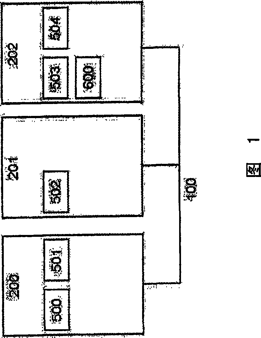
[0063] Assume a FlexRay network 100 in which three ECUs 200, 201, 202 are connected. ECU 200 carries software applications 500 and 501 , ECU 201 carries software application 502 , and ECU 202 carries software applications 503 and 504 and additionally carries software application “Explorer” 600 .
[0064] It is assumed that the software application 502 is an application which does not implement the method described here and only wants to use the FlexRay bus system for data exchange in a conventional manner.
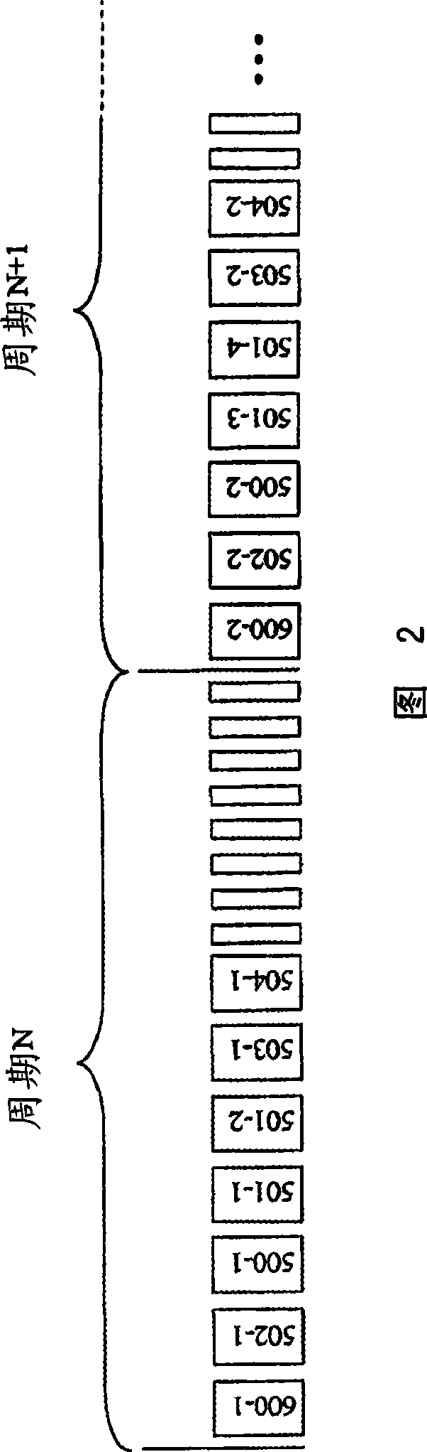
[0065] The communication cycle of the FlexRay bus system is divided into static and dynamic segments. The methods described here should be applied to dynamic segments. It should be pointed out here that the static segment of the FlexRay communication cycle does not correspond to the communication system characteristics explained above.
[0066] Now, at development time configure the dynamic segment of the FlexRay communication cycle such that it lasts i milliseconds. Un...
example 1
[0075] It is assumed that all software applications want to actually use the time slots allocated to them for data transmission and leave no time slots unused. Then in the first time slot, the software application 502 first transmits the duration i / 2. Next, the software application 500 likewise transmits the duration i / 2 in time slot 2 . Now, the communication cycle is over, and slots 3 to 6 have not been reached. Software applications 501, 503 and 504 cannot transmit data during this period. The resource manager 600 has advantageously made the allocation of time slots precisely such that just those messages whose transmissions have generated the greatest usage can be transmitted, while just those messages whose contribution to the overall usage may have lesser consequences for the overall usage are not transmitted.
PUM
 Abstract
Description
Claims
Application Information