Machine for processing head of pipe fitting

A technology of pier head machine and pipe fittings, which is applied to swage forging presses, upsetting forging presses, driving devices of forging presses, etc., can solve the problems of insufficient joint pipe strength, difficulty in meeting requirements, high production costs, etc., and achieve easy operation, Easy processing and long service life

Inactive Publication Date: 2009-03-04
庄添财
View PDF0 Cites 12 Cited by
  • Summary
  • Abstract
  • Description
  • Claims
  • Application Information

AI Technical Summary

Problems solved by technology

Using traditional technology to produce this kind of joint pipe, the process is complicated, the processing is difficult, the production cost is high, and the strength of the joint pipe is not enough to meet the requirements

Method used


Image

  • Machine for processing head of pipe fitting
  • Machine for processing head of pipe fitting
  • Machine for processing head of pipe fitting

Examples


Embodiment Construction

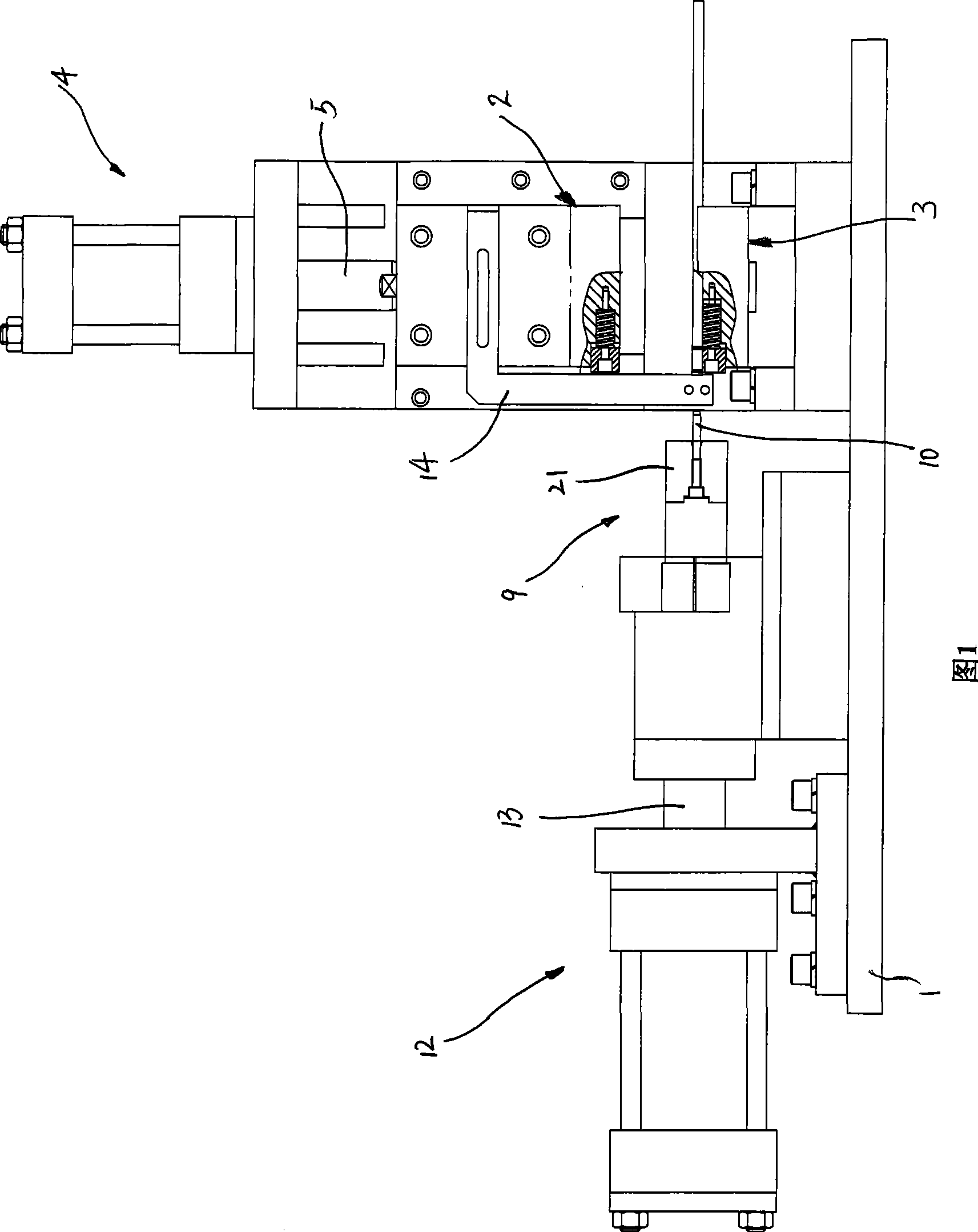
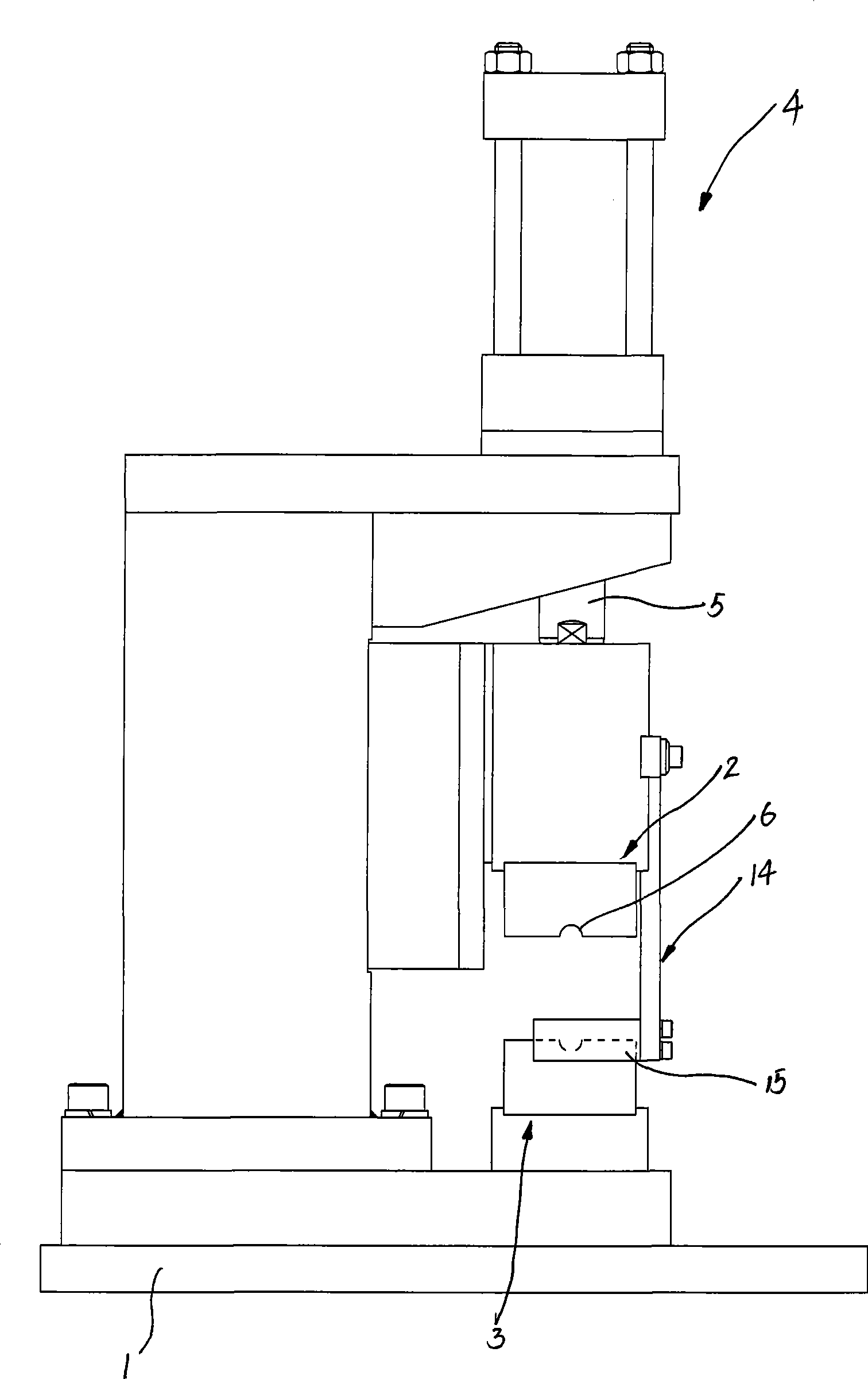
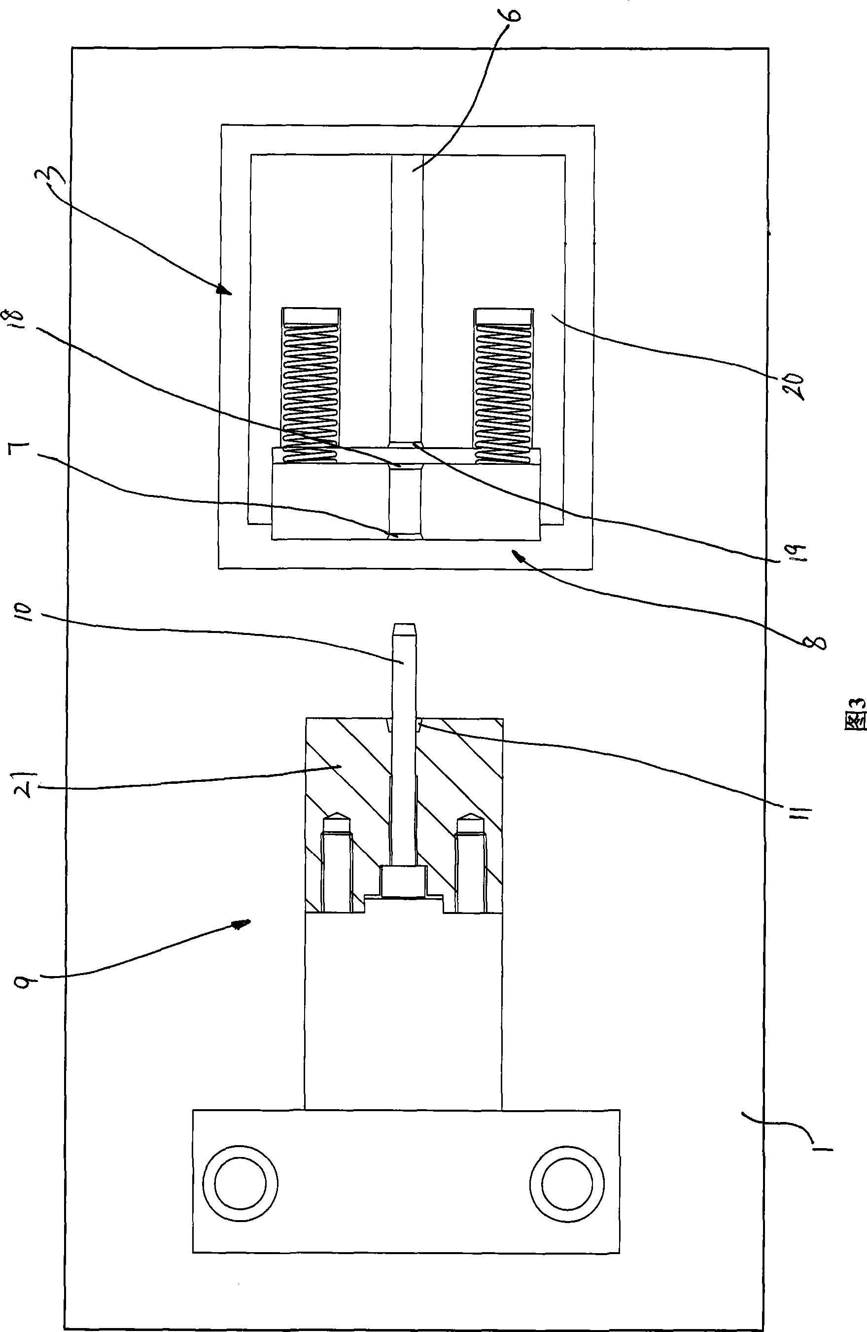
[0016] Referring to accompanying drawings 1 to 3, a pipe fitting heading machine includes a frame 1, a first die 2 arranged on the frame 1, a die set on the frame 1 The second die 3 , the pier head 9 located at the rear side of the first die 2 and the second die 3 , and the pier head 9 is movably arranged on the frame 1 . The frame 1 is fixedly provided with a first cylinder 4, the first cylinder 4 has a first piston rod 5 arranged in the vertical direction, and the first die 2 is fixedly connected to the first cylinder. on a piston rod 5, and the first die 2 is located directly above the second die 3 (the positional relationship of "up" and "down" described in this specification is the same as that shown in Figure 1 Corresponding to the upper and lower positional relationship).

[0017] The opposite side surfaces of the first die 2 and the second die 3 are provided with grooves 6 extending in the horizontal direction, and the projection of the longitudinal section of the gro...


PUM


Abstract

The invention relates to a pier head machine for pipe fittings which comprises a stander, a first moulding die, a second moulding die and a pier head. Grooves are formed on the opposite side surfaces of the first moulding die and the second moulding die; a flaring groove part is formed at the rear end of the groove; the pier head is composed of a pier part and a piercing pole; a flaring groove is formed on the pier part. When the pier machine of pipe fittings is in a first working state, the first moulding die is bonded with the second moulding die; the front end surface of the pier part is propped against the back end surface of the first moulding die and the second moulding die; a pair of grooves are butted to form a cavity used for placing the pipe pieces; the piercing pole is inserted in the pipe fittings; the flaring groove part is butted with the flaring groove to form a space used for entering into the pipe wall. Compared with the prior art, the heading machine has the advantages of convenient and quick processing and easy operation; in addition, the pipe wall of the joint pipe processed by using the pier head machine has even thickness, thereby meeting higher strength requirements and having longer service life.

Description

technical field [0001] The invention relates to a piercing machine for pipe fittings, which belongs to pipe fitting processing equipment. Background technique [0002] In the prior art, joint pipes are widely used in oil circuits of automobiles, or pipeline circuits of circulating fluids of refrigerators and air conditioners. As shown in FIG. 5 , the pipe wall of the joint pipe has an outwardly protruding annular protrusion, so that it can be tightly combined with the matching sleeve. These ring-shaped protrusions are usually formed by looping the ordinary pipe fittings, and then welding the two together; or expanding the heads of the two pipe fittings respectively, and then butt-joining and welding the two pipe fittings. The production of such joint pipes by using traditional technology is complicated in process, difficult in processing, high in production cost, and the strength of joint pipes is not enough to meet the requirements. Contents of the invention [0003] Th...

Claims


Application Information

Patent Timeline
Patent Type & Authority Applications(China)
IPC IPC(8): B21J5/06B21J9/06B21J9/12B21J13/02
Inventor 王伟薛晓马
Owner 庄添财
Why Eureka
Try Eureka