Storage box structure for vehicle

A technology for storage boxes and vehicles, which is applied in the passenger space and other directions, can solve the problems of reducing the number of occupants and reducing the space for seating arrangements, and achieves the effect of improving convenience and ensuring habitability.

Inactive Publication Date: 2009-03-04
MAZDA MOTOR CORP
View PDF1 Cites 15 Cited by
  • Summary
  • Abstract
  • Description
  • Claims
  • Application Information

AI Technical Summary

Problems solved by technology

However, in the structure of the above-mentioned patent document in which the storage box is mounted on the floor portion between a pair of seats arranged side by side in the vehicle width direction, there i

Method used


Image

  • Storage box structure for vehicle
  • Storage box structure for vehicle
  • Storage box structure for vehicle

Examples


no. 1 example

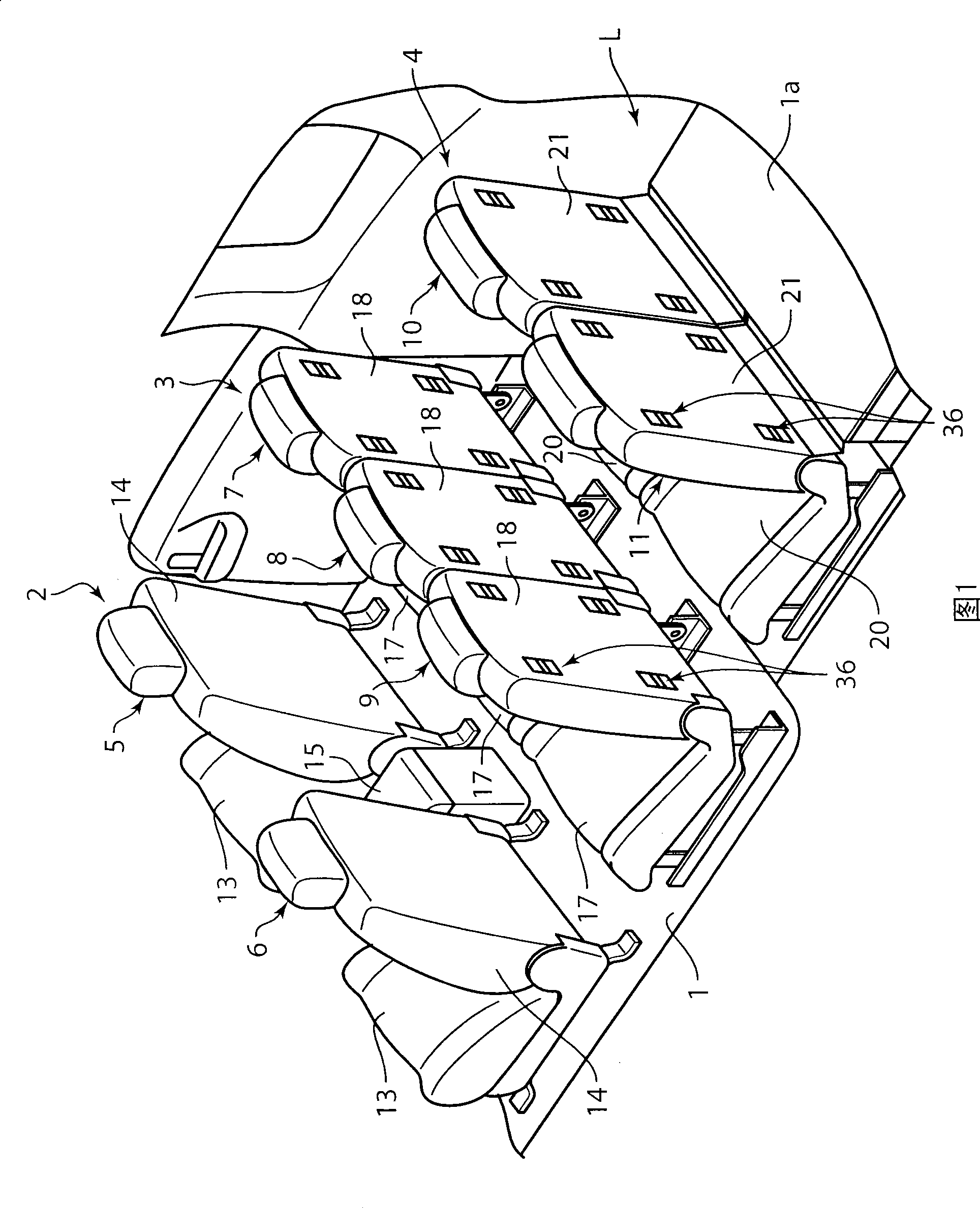
[0050] Fig. 1 is a schematic view of the first embodiment of the installation structure of the vehicle storage box of the present invention. In the vehicle compartment of the vehicle shown in this figure, a first seat row 2 composed of a driver's seat 5 and a passenger's seat 6 is provided on the front portion of the floor 1 constituting the bottom surface of the vehicle compartment, and at the same time behind it. On the side, the second and third seat rows 3 composed of a plurality of seats (unit seats 7 to 9 and unit seats 10 and 11 to be described later) arranged side by side in the vehicle width direction are arranged sequentially from front to back. , 4. In addition, since the vehicle in this embodiment is a right steering wheel vehicle, the right seat in the first seat row 2 is the driver's seat 5 , and the left seat is the passenger's seat 6 .

[0051] The driver's seat 5 and the passenger's seat 6 constituting the first seat row 2 each have a seat cushion 13 forming ...

no. 2 example

[0086] Fig. 15 and Fig. 16 are schematic diagrams of the second embodiment of the installation structure of the vehicle storage box of the present invention. As shown in the above figure, the storage box 60 of this embodiment has a main body 62 , a pair of left and right armrest members 64 provided on the upper side of the main body 62 , and a table member 63 provided between the left and right armrest members 64 .

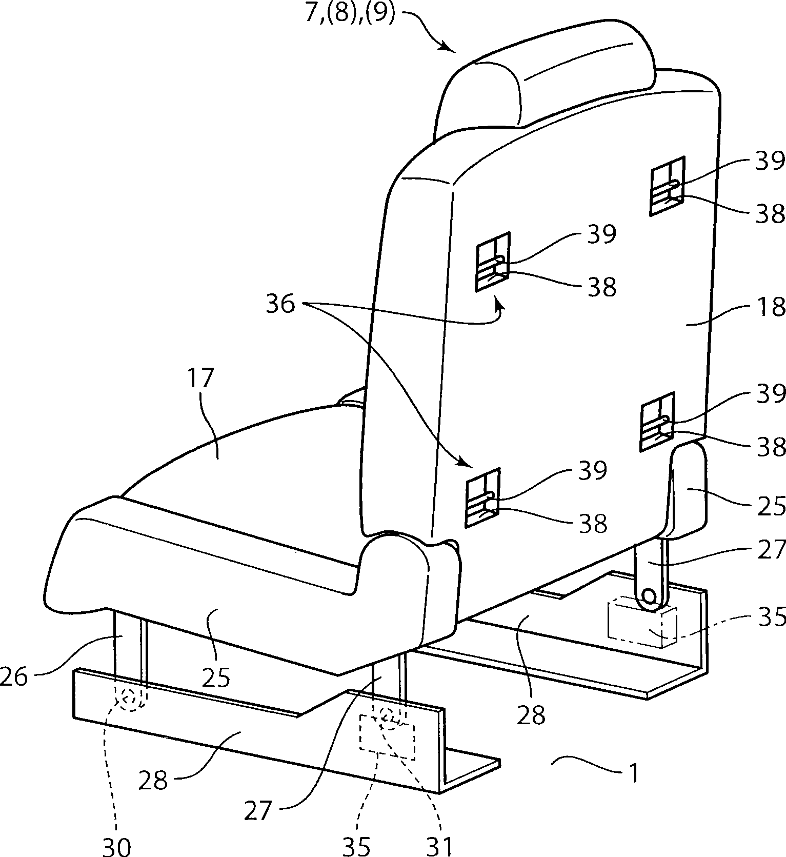
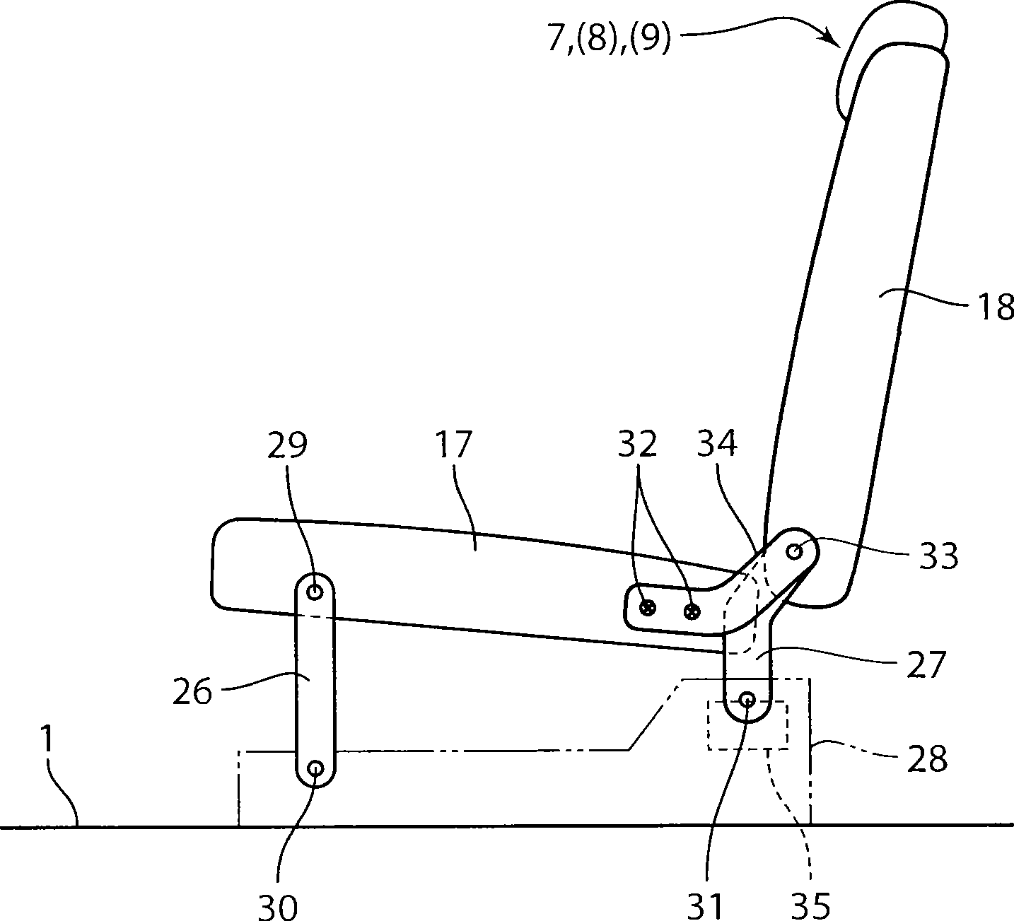
[0087] The storage box 60 is installed in a state where the backrest 18 of the unit seat 8 located at the center in the vehicle width direction among the unit seats 7 to 9 constituting the second seat row 3 is laid down on the seat cushion 17 as shown in the figure. Use on the back of the reclining backrest 18 . Therefore, on the back of the backrest 18 of at least the above-mentioned unit seat 8 in the above-mentioned second seat row 3, a figure 2 The case supporting part 36 shown in the above-mentioned case, by locking on this case supporting part 36 the hook p...


PUM


Abstract

Disclosed is a storage box structure for a vehicle having a plurality of unit seats 5, 6, 7 to 9, 10, 11 each provided on a floor panel 1 to serve as a passenger seat. The storage box structure comprises a storage box 40 adapted to store an article therein and to be releasably locked relatively to a box support portion 36 provided to a back surface of a seat back (18, 21) of at least one of the unit seats. The seat back (18, 21) of the at least one unit seat is supported displaceably between a standing position where it stands upwardly, and a folded position where it is folded down on a seat cushion (17, 20) of the at least one unit seat. The storage box 40 includes a box body 42 having a storage space 41 defined to be opened upwardly when the box body 42 is supported relative to the back surface of the seat back (18, 21) set in the folded position, and a lid member 43 adapted to openably close a top opening of the box body 42. The storage box structure of the present invention can achieve an excellent balance between ensuring of a maximum seating capacity and improvement in usability of the storage box.

Description

technical field [0001] The present invention relates to a storage box installation structure for a vehicle. In the storage box installation structure for a vehicle, a plurality of seats provided with a seat cushion and a backrest rising upward from the rear end of the seat cushion are provided on a floor for use in The storage box for storing articles is supported on the back of the backrest of at least one of the seats. Background technique [0002] In the past, a structure disclosed in Japanese Patent Laid-Open Publication No. 2006-21608 is known. In this structure, the storage box for storing articles used in the vehicle interior is installed on the bottom surface of the storage box. The engagement unit is capable of engaging with the striker provided at multiple places on the floor portion (floor) of the vehicle compartment, so that it can be selectively installed at multiple places in the vehicle compartment. [0003] Specifically, in the above-mentioned patent documen...

Claims


Application Information

Patent Timeline
IPC IPC(8): B60R7/04
Inventor 楠弘隆富田俊彦田畑孝司松冈完井冈忠士
Owner MAZDA MOTOR CORP
Why Eureka
Try Eureka