Structure improvement of electromagnetic pump

A pumping and electromagnetic technology, applied in the direction of pumps, pumps with flexible working elements, liquid variable capacity machinery, etc., can solve problems such as insufficient suction

Inactive Publication Date: 2009-03-04
邱浚腾
View PDF0 Cites 3 Cited by
  • Summary
  • Abstract
  • Description
  • Claims
  • Application Information

AI Technical Summary

Problems solved by technology

[0002] The electromagnetic pump has the characteristics of low noise, low power consumption, long-term use, and no high heat, so its related applications are extremely extensive. It was used in aquarium pumping in the early days, such as No. 082201395 "Structure Improvement of Aquarium Pumping Pump" ”A new type of patent, and some manufacturers also apply it to anti-decubitus air mattresses, such as the new patent No. 092218142 "Inflatable device for air mattresses", and then extend it to apply to nasal aspirators, such as No. 095200851 "With multiple suction frequencies Nasal aspirator", please refer to Fig. 1 and shown in Fig. 2 again, the basic structure of electromagnetic pump 10 is nothing more than an electromagnetic device 11 and an air chamber 12, and this air chamber 12 is a hollow casing, and its outer One to several input conduits 121 and output conduits 122 are arranged on the side, and there are flow passages (not shown in the figure) for fluid flow inside, which communicate with the input conduit 121 and the output conduit 122. The outer surface of the air chamber 12 has a convex seat 18 respectively. Each convex seat 18 is sleeved with a hollow rubber cap 15, each rubber cap 15 is set together with a vibrating crank 13, and one end of each crank 13 is sleeved with a rubber rotating shaft 16, and each rotating shaft 16 is tightly embedded in the air In the pivot seat 17 on the other side of the chamber 12, a magnet 14 is arranged at the other end to face the electromagnetic device 11. When the electromagnetic pump 10 is started, the magnets 14 at one end of the two vibrating cranks 13 are switched by the magnetic field generated by the electromagnetic device 11. The vibrating crank 13 vibrates repeatedly outwardly and inwardly, so that the fluid can be pumped from the input conduit 12 end to the output conduit 122 end; It does not have any obvious disadvantages, but when it is applied to a nasal aspirator, there is a situation of insufficient suction. When it is applied to an air mattress, it must take a long time to get enough gas for the air mattress; The design key point of increasing the suction force of the electromagnetic pump 10 and the flow rate of the fluid must increase the overall volume, amplify the electromagnetic field of the electromagnetic device 11, and increase the vibration frequency of the two vibrating cranks 13. The conventional electromagnetic pump 10 is After the above-mentioned improvement, after the actual test, although the situation of insufficient suction and flow can be solved, it cannot be used for a long time, probably because the rotating shaft 16 at the pivot end of the two vibrating cranks 13 is made of rubber material. After the vibration frequency is higher, each rotating shaft 16 generates high heat due to excessive friction, and then melts and deforms, making the two vibrating cranks 13 vibrate asymmetrically, and cannot do work effectively; therefore, the known electromagnetic pump Pu 10 needs to be improved

Method used


Image

  • Structure improvement of electromagnetic pump
  • Structure improvement of electromagnetic pump
  • Structure improvement of electromagnetic pump

Examples


Embodiment Construction

[0043] In order to make your examiner and those who are accustomed to this technique have a further understanding of the present invention, a preferred embodiment is given hereafter, and the details are as follows: (but, this embodiment is only beneficial to explanation, and the future development of the present invention Implementation is not limited to this, and all improvements and implementations based on the technical features of the present invention are bound by the present invention).

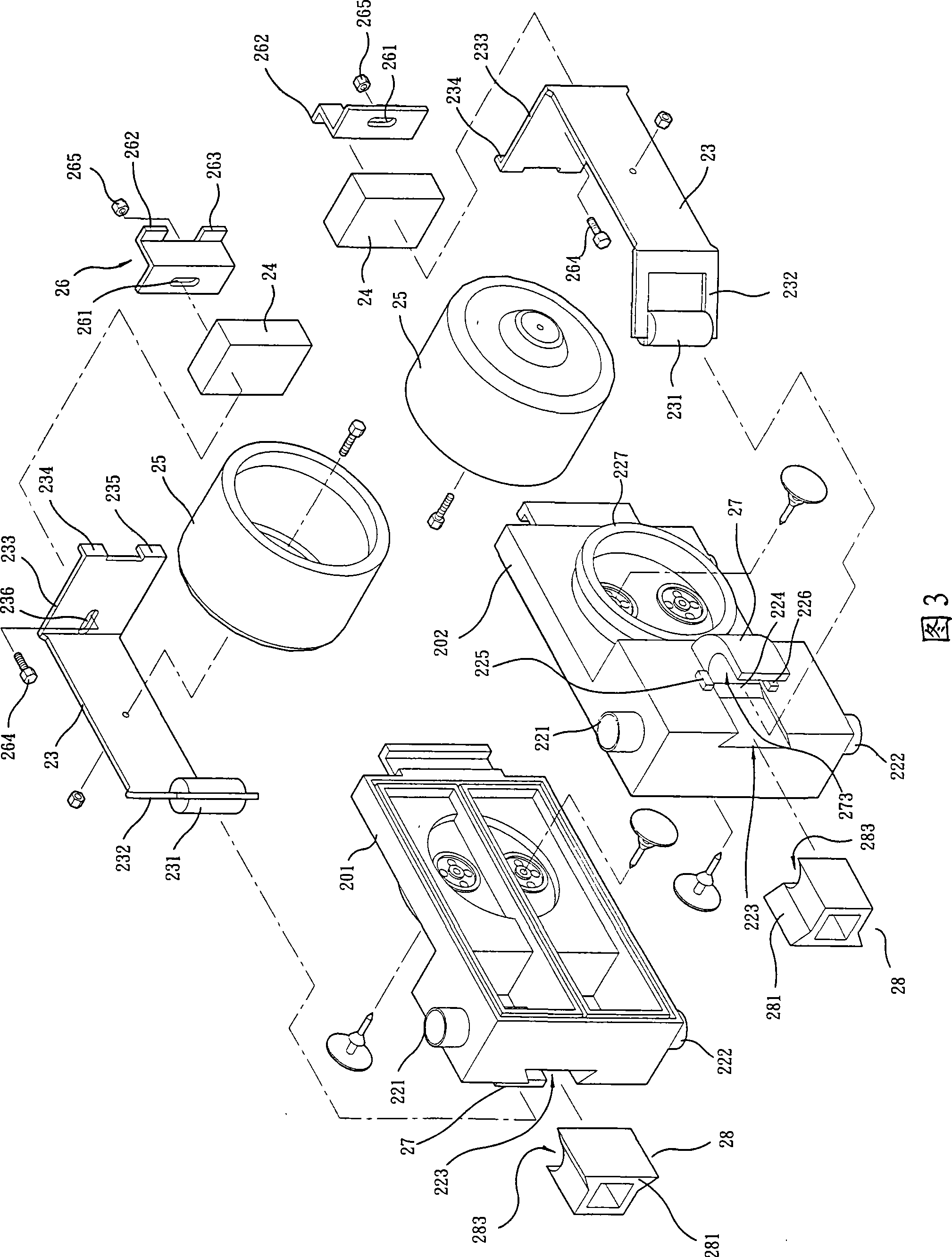
[0044]Please refer to Fig. 3 to Fig. 6, the air chamber 22 of the electromagnetic pump 20 of this embodiment is formed by the first shell 201 and the second shell 202 being fixed together, the first shell 201, the second shell Body 202 is made of wear-resistant material, and the wear-resistant material can be plastic steel, ceramics, Teflon, the inner compartment of the air chamber 22 is divided into two inner spaces, and one to several input conduits 221 and output conduits are provided...


PUM


Abstract

The present invention relates to an improvement of the structure of an electromagnetic pump. The improvement mainly increases the suction and discharge force and flow of the electromagnetic pump, but still, the electromagnetic pump can operate properly. While increasing the suction and discharge force and flow of the conventional electromagnetic pump, the improvement can ensure that two vibrating cranks cannot asymmetrically vibrate to cause the malfunction of the electromagnetic pump. The improvement mainly sleeves a rotary shaft made of wearable material on the pivotal end of each vibrating crank; the rotary shafts clamp each other in a pivotal state by means of pivotal seat and tabling blocks arranged on both outer sides of an air chamber; the opposite sides of each pivotal seat and each tabling block form a concave arc-shaped notch in which a rotary shaft can be contained; and the pivotal seats and the tabling blocks are also made of the wearable material. With the structure design, the improvement not only can increase the suction and discharge force and flow of the electromagnetic pump but also can ensure that the rotary shafts of the vibrating cranks cannot generate high temperature due to friction and deform, thus ensuring the normal operation of the electromagnetic pump.

Description

technical field [0001] The invention provides an improved electromagnetic pump structure. Background technique [0002] The electromagnetic pump has the characteristics of low noise, low power consumption, long-term use, and no high heat, so its related applications are extremely extensive. It was used in aquarium pumping in the early days, such as No. 082201395 "Structure Improvement of Aquarium Pumping Pump" ”A new type of patent, and some manufacturers also apply it to anti-decubitus air mattresses, such as the new patent No. 092218142 "Inflatable device for air mattresses", and then extend it to apply to nasal aspirators, such as No. 095200851 "With multiple suction frequencies Nasal aspirator", please refer to Fig. 1 and shown in Fig. 2 again, the basic structure of electromagnetic pump 10 is nothing more than an electromagnetic device 11 and an air chamber 12, and this air chamber 12 is a hollow casing, and its outer One to several input conduits 121 and output condui...

Claims


Application Information

Patent Timeline
Patent Type & Authority Applications(China)
IPC IPC(8): F04B45/047
Inventor 王铭阳
Owner 邱浚腾
Why Eureka
Try Eureka