Diverter for grounding wire

A technology of steering gear and grounding wire, which is applied in the direction of connection, conductive connection, and electrical component connection, etc. It can solve the problems of difficulty in hanging and removing the grounding wire of the tension tower, inconvenient mounting and detaching of the grounding wire, and inability to use it, so as to achieve saving The effect of manpower and labor intensity, convenient operation, and accurate mounting process

Inactive Publication Date: 2010-08-11
SUZHOU POWER SUPPLY COMPANY OF STATE GRID ANHUI PROVINCE ELECTRIC POWER +1
View PDF0 Cites 0 Cited by
  • Summary
  • Abstract
  • Description
  • Claims
  • Application Information

AI Technical Summary

Problems solved by technology

However, in fact, after the operating rod 6 is released from the hand, the position is moved along with the action of gravity, and when the ground wire is removed, the operating rod 6 (as shown in Figure 3 ) can be hooked without being borrowed by other items. Sometimes it is very inconvenient to be tied on the operating rod 12 with a rope; it is very difficult to hang the ground wire and remove the ground wire at the tension wire clip hanging point of the tension pole tower. Basically, it cannot be used in work like this. It is difficult to hang the wire into the ditch tightly. Even if it is hung up, the operating rod will move in the opposite direction of the tower under the action of gravity. When the grounding wire is removed, the operating rod cannot be grasped, and it is very inconvenient to hang and remove the grounding wire
[0004] According to the existing technical situation, when a power outage replaces a base tension insulator string, the grounding wire is usually hung on the two adjacent towers of the working tower, and the number of climbing towers is two bases more. If the insulator strings at both ends are hung up, there is no need to climb the adjacent two-level towers, reducing the number of climbing times by 50%, reducing the amount of high-altitude operations by 30%, and reducing the working time by 30%, which relatively speaking improves the safety of personnel. coefficient, which reduces the labor intensity and shortens the power outage time of the transmission line, but the existing technology cannot achieve this situation

Method used


Image

  • Diverter for grounding wire
  • Diverter for grounding wire
  • Diverter for grounding wire

Examples


Embodiment Construction

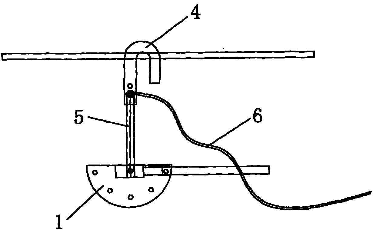
[0021] Referring to Fig. 4 and Fig. 5, a semicircular steering wheel 1 is set, and the semicircular steering wheel 1 has a center hole 2 at the center of the circle and steering holes 3 at different angle positions on the circumference, and the straight rod 5 connected with the hook 4 is fixed. Linked to the central hole 2, the steering rod 7 connected to the operating rod 6 is hinged on the central hole 2 with its rod end, and fixed in the steering hole 3 with the adjustment hole at the corresponding position. A set angle of rotation is formed with the steering rod 7 .

[0022] Referring to Fig. 4 and Fig. 5, a semicircular steering wheel 1 is set, and the semicircular steering wheel 1 has a center hole 2 at the center of the circle and steering holes 3 at different angle positions on the circumference, and the straight rod 5 connected with the hook 4 is fixed. Linked to the steering wheel 1, the steering rod 7 connected with the operating rod 6 is hinged on the center hole 2...


PUM


Abstract

The invention relates to a steering device of a grounding wire, which is characterized in that a semicircular steering wheel is arranged and provided with a center hole at the center position of a circle and a steering hole at the position of the circumference with different angles; a straight rod connected with a hook is fixedly coupled on the steering wheel; the rod end of a steering rod connected with an operating rod is articulated on the center hole, an adjusting hole at the corresponding position of the steering rod is fixed in the steering hole with the set angle, and a set rotating angle is formed between the straight rod and the steering rod. The invention can lead the mounting and dismounting of the grounding wire to be more convenient and faster, improve the work efficiency of electric power overhauling and improve the safety of operation.

Description

technical field [0001] The invention relates to an electric facility maintenance tool. Background technique [0002] Grounding the three-phase short-circuit of the power-off equipment is the most reliable protection measure to ensure that the staff are not injured by electric shock. All equipment that may send power to the power-off equipment or that may generate induced voltage should be installed with a grounding wire. For power outage maintenance of transmission lines, the grounding wire is a necessary safety tool to ensure the safety of transmission line power outage maintenance workers, and it is also an important part of power outage maintenance work. [0003] The grounding device currently used is as shown in Figure 1. The top of the grounding wire 11 is connected to a spring hook 12, and the spring hook 12 is hooked on the three-phase line, and the other end of the grounding wire 11 is dragged to the The ground is grounded. In order to hook the spring hook 12 to the...

Claims


Application Information

Patent Timeline
Patent Type & Authority Patents(China)
IPC IPC(8): H01R11/14
Inventor 张永张明
Owner SUZHOU POWER SUPPLY COMPANY OF STATE GRID ANHUI PROVINCE ELECTRIC POWER
Why Eureka
Try Eureka