Bracket for antenna attachment

a bracket and antenna technology, applied in the field of brackets, can solve the problems of difficult to reconcile two requirements, difficult to achieve the height of the antenna, etc., and achieve the effect of minimizing the overall height of the antenna and its, low profile, and convenient use and maintenan

Active Publication Date: 2017-04-11
WIRELESS CONSTR INC
View PDF19 Cites 2 Cited by
  • Summary
  • Abstract
  • Description
  • Claims
  • Application Information

AI Technical Summary

Benefits of technology

[0006]It is an object of the present invention to provide an antenna bracket configured to enable adjustment of an antenna such as a cellular signal transmission / reception antenna on its support so that it is aligned in a desired position. It is also an object of the present invention to provide such an antenna bracket that is relatively low profile to minimize the overall height of the antenna and its support. The antenna bracket is designed to be relatively easy to use and maintain so that it can be placed on the support structure and keep the antenna in a desired alignment under expected weather conditions.
[0007]These and other objects are achieved with the present invention, which is an antenna bracket that enables relatively easy alignment of the antenna on its support. It also enables relatively low profile placement of the antenna on the support so that the antenna is located a small distance from the top of the support without compromising the ability to align the antenna where desired. This present bracket helps with antenna concealment and provides a stable mount for antenna optimizations.
[0010]The bracket of the present invention adds only a few inches to the overall height of the support and antenna combination. As a result, the antenna has a very low profile and thereby is fairly well concealed while also aiding in meeting overall height restrictions. The bracket members may be fabricated of relatively inexpensive materials such as steel, aluminum or other metallic and non-metallic materials. The alignment device may be a trailer ball, which is also relatively inexpensive. Its curved member allows for fine movement of the antenna without limitation to a single plane of movement. In addition, the use of the present alignment device as part of the bracket facilitates antenna placement, alignment and securing, thereby improving the installation process and any adjustment or maintenance efforts that may be required.

Problems solved by technology

It is difficult to do that at the heights involved.
These two requirements can be difficult to reconcile as spacing the antenna from the top of the support generally enables more effective alignment.

Method used


Image

  • Bracket for antenna attachment
  • Bracket for antenna attachment
  • Bracket for antenna attachment

Examples


Embodiment Construction

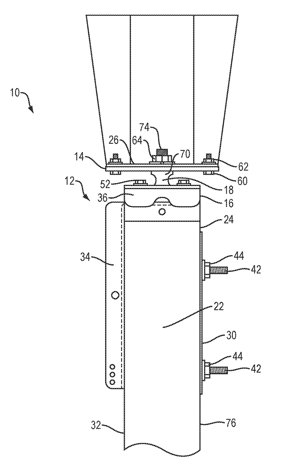
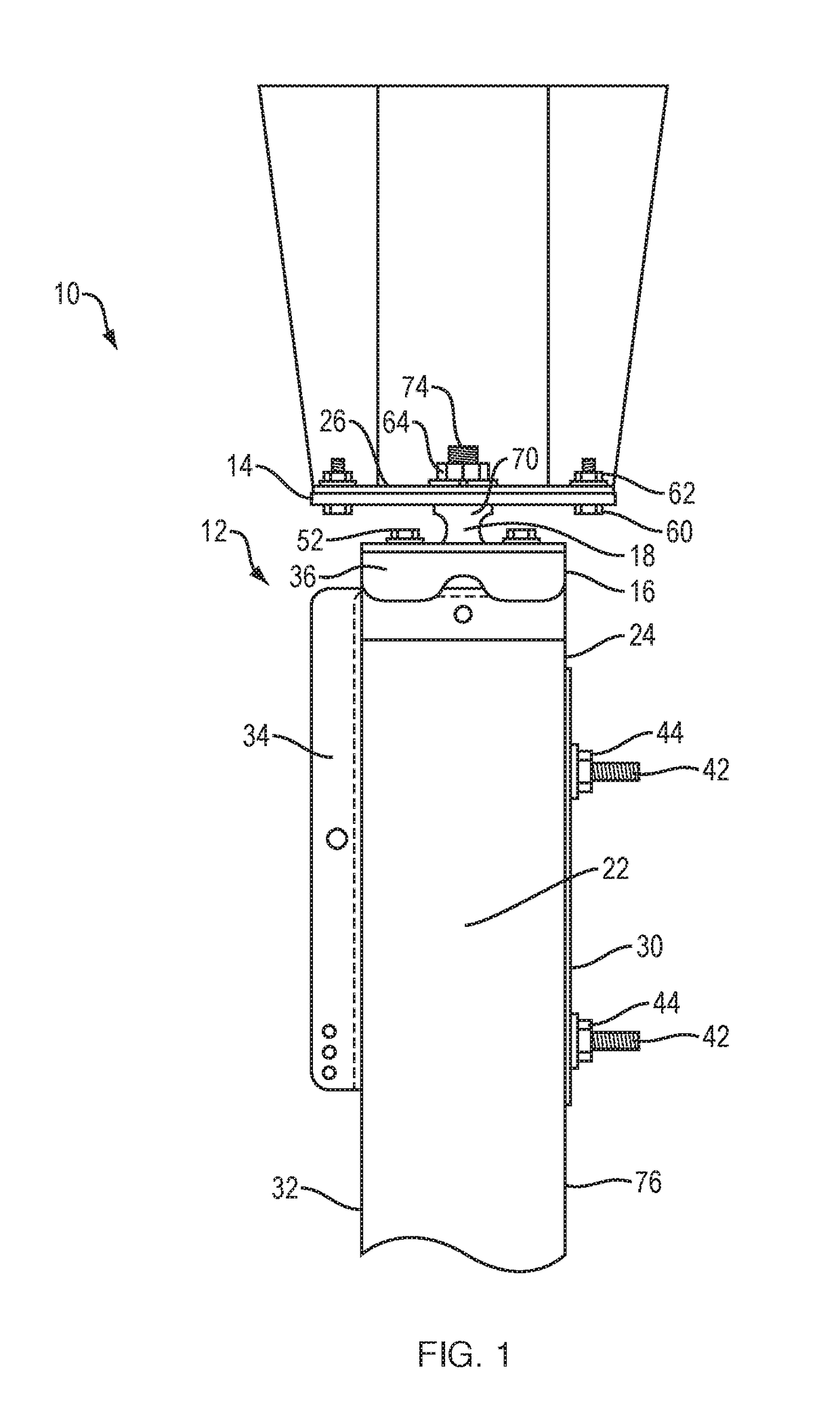
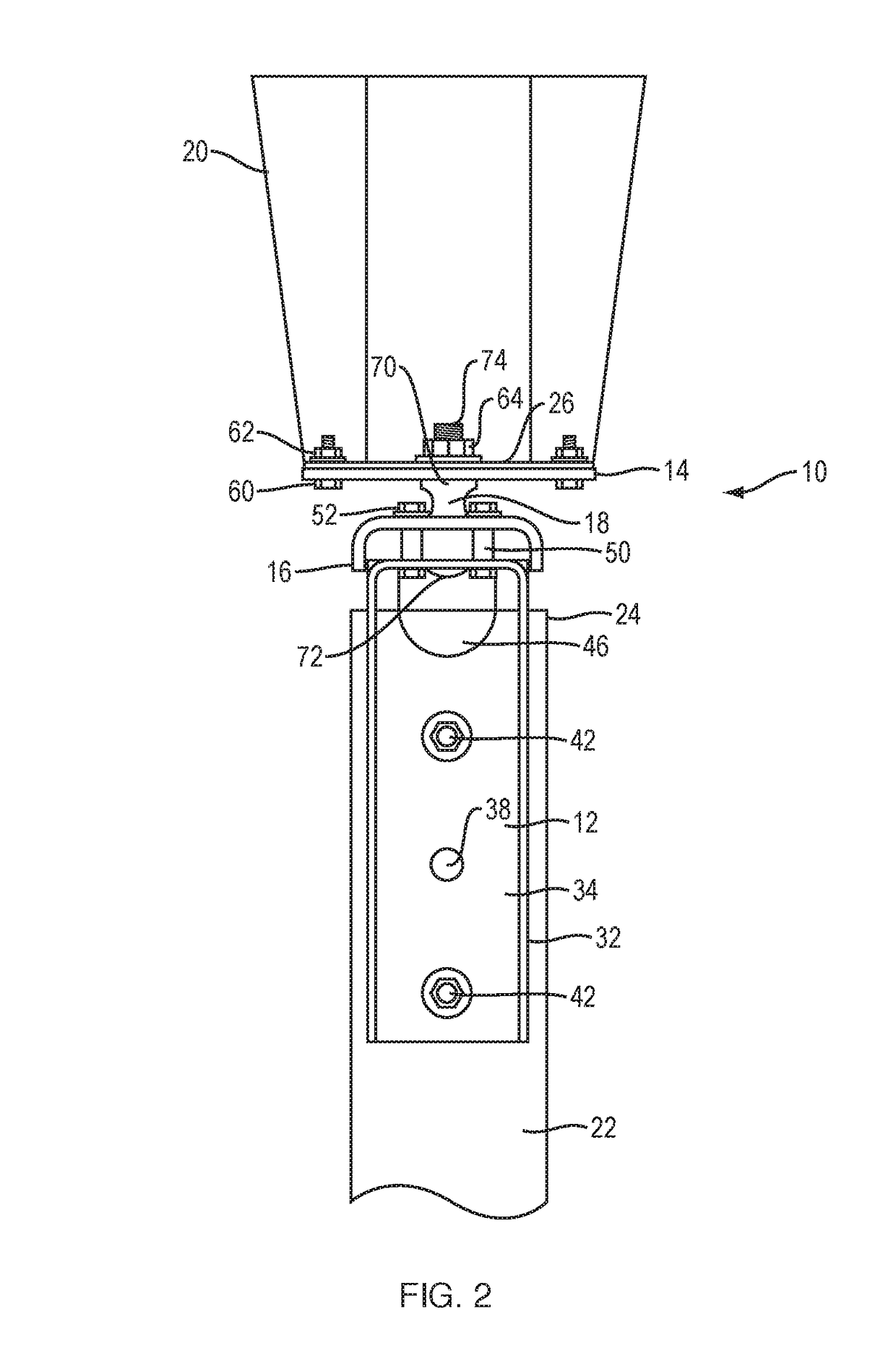
[0026]An antenna bracket 10 of the present invention is shown in FIGS. 1 and 2. The bracket 10 includes a first bracket member 12, a second bracket member 14, a bracket interface member 16 and an alignment device 18. The antenna bracket 10 is configured to affix an antenna 20 to an antenna support structure 22, which may be a utility pole, for example. The bracket 10 is an adjustable interface between a top 24 of the support structure 22 and a bottom 26 of the antenna 20. The bracket 10 may include an optional backer plate 30 to aid in securing the first bracket member 12 to a side 32 of the support structure 22.

[0027]As illustrated in FIGS. 1-5, the first bracket member 12 is of an angled structure including a first leg 34 and a second leg 36. The first bracket member 12 may be made of steel or other suitable material and either or both may be channel shaped. The first leg 34 is configured to join the first bracket member 12 to the side 32 of the support structure 22. The first leg...


PUM


Abstract

An antenna bracket that enables relatively easy alignment of an antenna on a support structure such as a utility pole or tower. The bracket provides for low profile antenna attachment. The bracket includes a first bracket member that is joined to the support structure, a second bracket member that is coupled to the antenna, and a bracket interface member that is coupled to the first bracket member. An alignment device formed with a coupling body and a curved member extending from the coupling body is retained between the bracket interface member and the first bracket member and is secured to the second bracket member. The curved member enables fine movement of the antenna in any selectable direction to ensure its alignment with respect to the support structure.

Description

BACKGROUND OF THE INVENTION[0001]1. Field of the Invention[0002]The present invention relates to brackets used to attach antennas to supports such as utility poles. More particularly, the present invention relates to an antenna bracket that can be used to adjust the alignment of the antenna and fixing it in an aligned position.[0003]2. Description of the Prior Art[0004]Presently, antennas such as cellular phone antennas are mounted on support structures that extend 100 feet or more from the surface. They are mounted using mounting brackets. It is important that the antenna be aligned as accurately as possible to ensure optimization of signal exchange. It is difficult to do that at the heights involved. Also, given governmental regulations that restrict the height of the combination of support structure and antenna, the antenna is preferably located as close to the top of the support as possible so as not to exceed height limits of the combination. These two requirements can be diffi...

Claims


Application Information

Patent Timeline
Patent Type & Authority Patents(United States)
IPC IPC(8): H01Q1/12F16M13/02H01Q1/22B60D1/06
CPCH01Q1/1228F16M13/02H01Q1/125H01Q1/22B60D1/06H01Q1/12F16M11/14
Inventor SULLIVAN, MICHAELPURINGTON, KYLESALEK, CLEMENT J.BOOTHBY, TODD
Owner WIRELESS CONSTR INC
Why Eureka
Try Eureka