Flex connector and manufacturing process

a technology of flex connectors and manufacturing processes, applied in the direction of connection contact material, line/current collector details, electrical apparatus, etc., can solve the problems of unfavorable use of these conductors, and achieve the effect of convenient bending, flexing and even twisting of flex connectors

Active Publication Date: 2011-06-07
HAWORTH SPA +1
View PDF50 Cites 17 Cited by
  • Summary
  • Abstract
  • Description
  • Claims
  • Application Information

AI Technical Summary

Benefits of technology

[0009]The invention therefore relates to a flex connector for modular power distribution systems of this type which incorporates an inventive flexible...

Problems solved by technology

However, it can be undesirable to allow these conductors to remain exposed in use and as such, the inventive flex connector is provided with a f...

Method used


Image

  • Flex connector and manufacturing process
  • Flex connector and manufacturing process
  • Flex connector and manufacturing process

Examples


Embodiment Construction

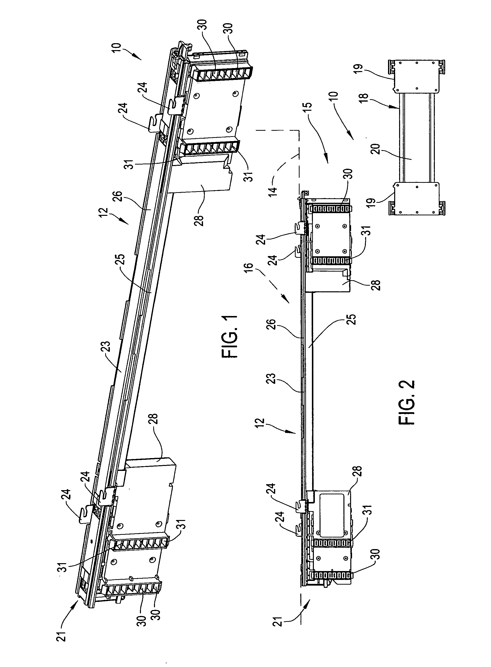
[0034]Referring to FIG. 1, the invention relates to an improved power distribution system 10 which is provided to route power throughout an office area. The power distribution system 10 includes various modular system components, which system components include a power distribution assembly 12 (PDA) which is adapted to be mounted within raceways of various building structures such as space-dividing wall panels, furniture or other static structures. The PDA 12 is configured to mount to wall panel frame rails or other similar static structure which is generally identified by reference numeral 14 (FIG. 2). The frame rail 14 or other similar structure typically defines a longitudinally extending raceway 15 in which the PDA 12 is mountable. The frame rail 14 extends along the length of a wall panel identified by reference numeral 16 wherein each PDA 12 has a length closely conforming to the length of the wall panel 16.

[0035]At the junction between adjacent wall panels 16, the power syste...


PUM

PropertyMeasurementUnit
Lengthaaaaaaaaaa
Flexibilityaaaaaaaaaa

Abstract

A modular power distribution system includes power distribution assemblies and flex connectors. The flex connector includes end connector housings and a flexible jacket that encloses conductor wires extending between the connectors. The jacket is formed from superimposed layers of sheet-like jacket material that is flexible. The bottom jacket layer is first laid on a bottom housing section wherein conductors are then placed thereupon with an upper jacket layer then positioned over the bottom jacket layer. The top and bottom jacket layers have aligned free edges along at least one side thereof wherein the free edges are bonded together such as by heat sealing.

Description

FIELD OF THE INVENTION[0001]The invention relates to a modular electrical power distribution system and more particularly, to an improved flex connector for such system having a flexible jacket and to an improved manufacturing process for assembling such flex connector.BACKGROUND OF THE INVENTION[0002]Modular power distribution systems are well known and comprise a plurality of modular electrical components which are connectable serially together to route power throughout an office area. These power distribution systems often include elongate power distribution assemblies (PDAs) which are mountable within raceways of conventional space-dividing wall panels, furniture or other static structures such as building raceways.[0003]One known power distribution assembly comprises an elongate rigid mounting rail which extends substantially along the length of a wall panel and supports a pair of connector blocks or power blocks on the opposite ends thereof. The support rail houses elongate el...

Claims


Application Information

Patent Timeline
IPC IPC(8): H01R4/60
CPCH02G3/0487H02G3/288Y10T29/49174
Inventor CROW, DEREKEMERY, DAVEKING, STEVEDANZ, DUANEDEYOUNG, JONATHAN R.ELZINGA, JASONWIERSEMA, MARKMOERLER, DOUGLEENSTRA, SCOTT
Owner HAWORTH SPA
Why Eureka
Try Eureka