Cable protection and guide device

A guiding device and cable protection technology, which is applied in the field of cable protection and guiding devices, can solve the problems of twisting and deformation of the link frame 501, hinder bending, and small fixing force, and achieve the effects of reducing twisting and deformation, smooth bending, and preventing upper separation

Active Publication Date: 2011-03-30
TSUBAKIMOTO CHAIN CO
View PDF6 Cites 13 Cited by
  • Summary
  • Abstract
  • Description
  • Claims
  • Application Information

AI Technical Summary

Problems solved by technology

[0007] However, in such a known cable protection and guiding device, the left and right pair of link plates 510, 520 and the connecting arm 540 only rely on the engagement of the hook portion 541 and the engaging shaft 513, 523, and the front end side of the hook portion 541 and the end surface abut against the wall. parts 514, 524 and the side surfaces of the hook part 541 and the side abutting wall parts 515, 525 are fixed, so there is the following problem: when the cable moves in the cable accommodation space and pushes upward When connecting the arm 540, because the fixing force of the connecting arm 540 is small, it is easy to disengage from above, thus creating an obstacle to the protection and guidance of the cable
[0008] In addition, there is a problem that when an external force is applied in the direction in which the link frame body 501 is twisted (that is, the direction in which the pair of left and right link plates 510, 520 become non-parallel), the pair of left and right link plates 510, 520 and the link arm 540 Only the hook portion 541 with a narrow width (the long side direction of the cable protection and guiding device) is fixed, so it is difficult for the connecting arm 540 to generate a large resistance to the force in this direction, so the connecting frame 501 is prone to twisting and deformation. thereby hindering its smooth bending

Method used


Image

  • Cable protection and guide device
  • Cable protection and guide device
  • Cable protection and guide device

Examples


Embodiment

[0044] Next, the cable protection guide device of the present invention will be described based on the drawings.

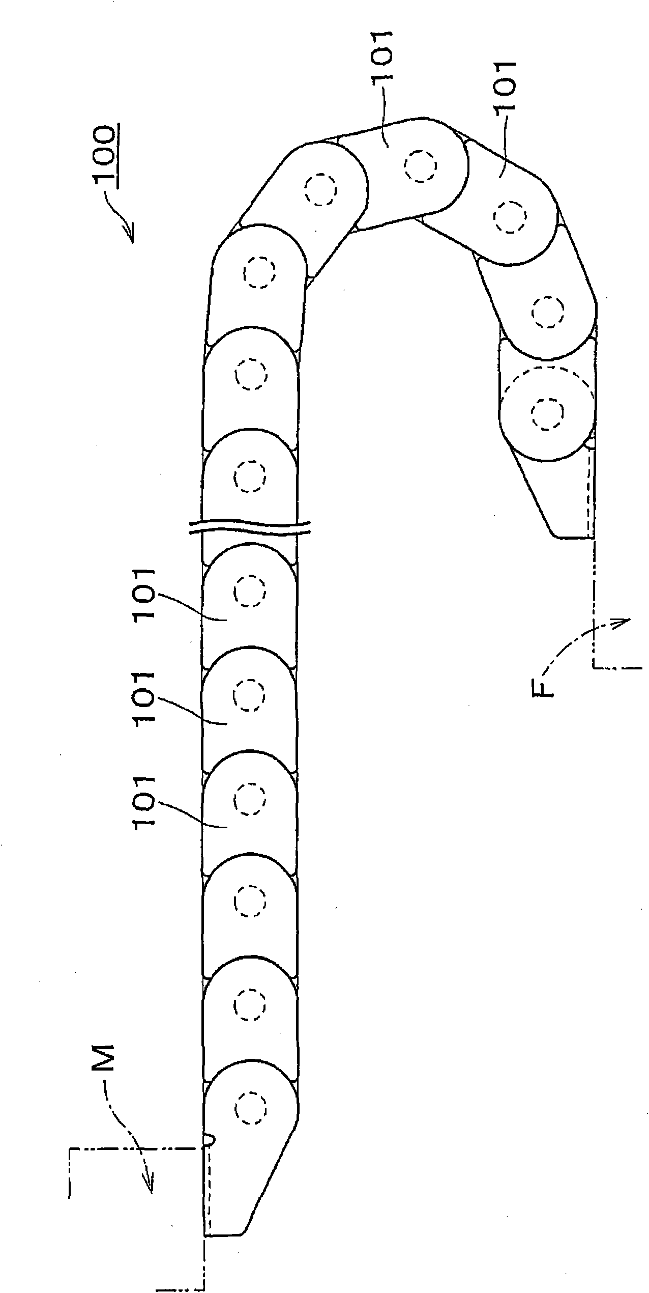
[0045] Such as figure 1 As shown, the cable protection and guiding device as an embodiment of the present invention is used for cables connecting the movable part M and the static part F in machine tools, electronic equipment, civil engineering, industrial manipulators, transmission devices, etc., for example Optical cables, cables for signal transmission or power supply, and hoses for supplying fluids such as oil pressure and air pressure are protected and guided.

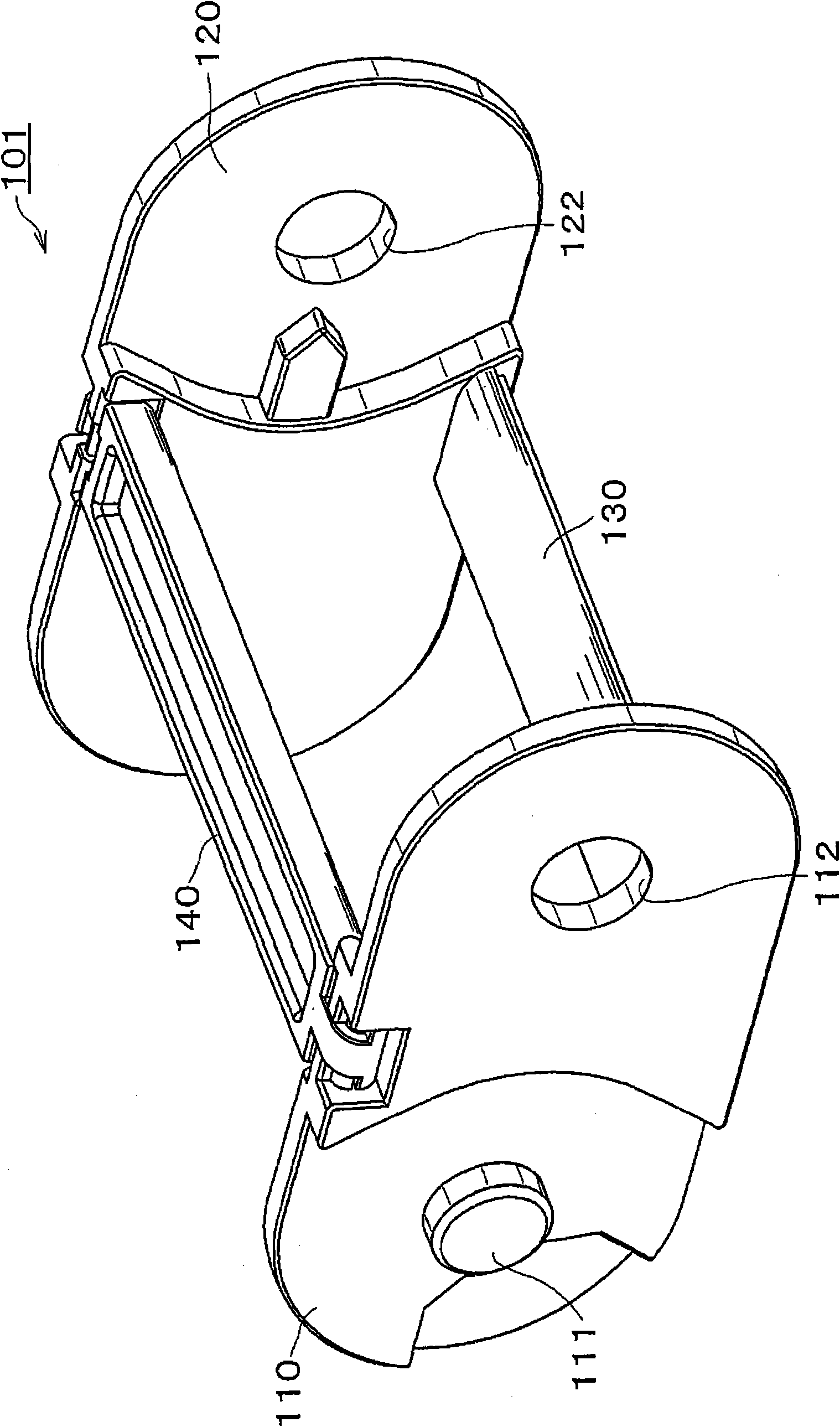
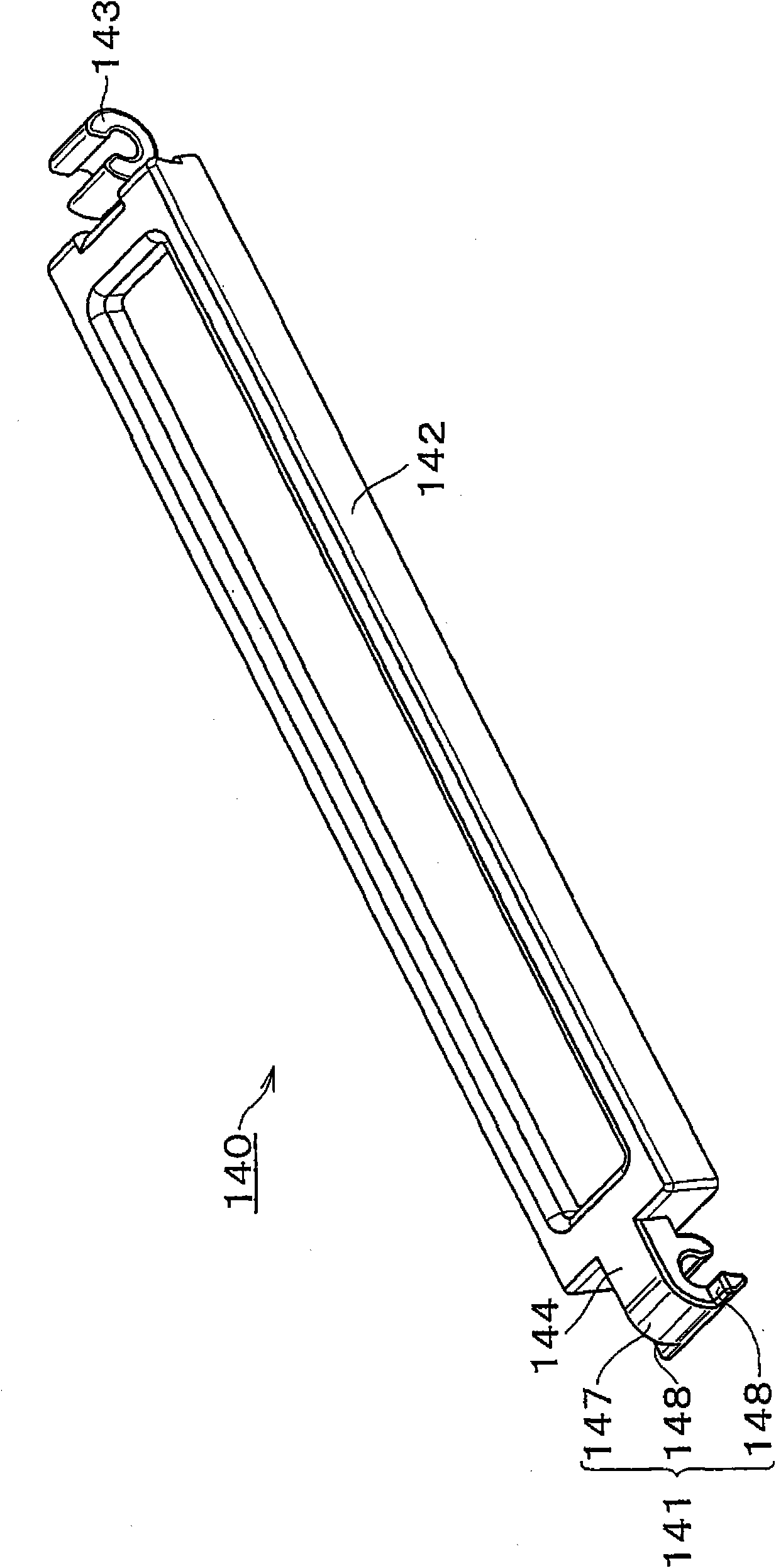
[0046] The cable protection and guiding device 100 is formed by connecting a plurality of link frames 101 to each other freely through the link pins and link pin holes provided on the link plates, wherein the link frame body 101 is composed of a pair of left and right link plates and frames arranged separately. The link plate is connected to the curved inner peripheral side of the link plate, and th...


PUM


Abstract

The invention provides a cable protection and guide device that steadily protects and guides a cable by rigidly anchoring and preventing a connecting arm from being disengaged upwardly. The device smoothly flexes and reduces torsional deformation. The hinged connecting arm extends across the flexional outer peripheral side of a pair of spaced apart right and left link plates and has a hook portion at one end of an arm body and a hinge portion at another end. An engaging circular arc portion of the hook portion engages with an engaging shaft of the link plate. Engaging projecting portions extend from the edge of the engaging circular arc portion and interengage with engaging step portions arranged on the engaging shaft.

Description

technical field [0001] The invention relates to a cable protection and guiding device, which is used in machine tools, electronic equipment, civil engineering machinery, industrial manipulators, conveying devices, etc., for cables that supply power, signal transmission, liquid supply, gas supply, etc. to the moving parts, Flexible cables, hoses, etc. (hereinafter, simply referred to as "cables") such as optical cables and fluid supply hoses provide safe and reliable protection and guidance. Background technique [0002] Conventionally, there is known a cable protection guide device, which is formed by connecting a plurality of link frames to each other flexibly through the link pins and the link pin holes provided on the link plate. A rectangular cable accommodation space is formed of a link plate, a link plate bridged on the curved inner peripheral side of the link plate, and a link arm bridged on the curved outer peripheral side of the link plate. [0003] Such as Figure...

Claims


Application Information

Patent Timeline
Patent Type & Authority Applications(China)
IPC IPC(8): F16L3/015
CPCY10S59/90F16L3/015F16G13/16H02G11/00
Inventor 小宫庄一郎山下胜英
Owner TSUBAKIMOTO CHAIN CO
Why Eureka
Try Eureka