Eureka AIR delivers breakthrough ideas for toughest innovation challenges, trusted by R&D personnel around the world.

Optical cable fanout device

a technology of optical cable and fanout device, which is applied in the direction of optics, fibre mechanical structures, instruments, etc., can solve the problems of affecting the transmission of optical signals, increasing costs, and interruption of optical signals, so as to prevent damage due to lateral tension and increase costs

Inactive Publication Date: 2018-05-31
COMMSCOPE TELECOMM (SHANGHAI) CO LTD
View PDF19 Cites 13 Cited by
  • Summary
  • Abstract
  • Description
  • Claims
  • Application Information

AI Technical Summary

Benefits of technology

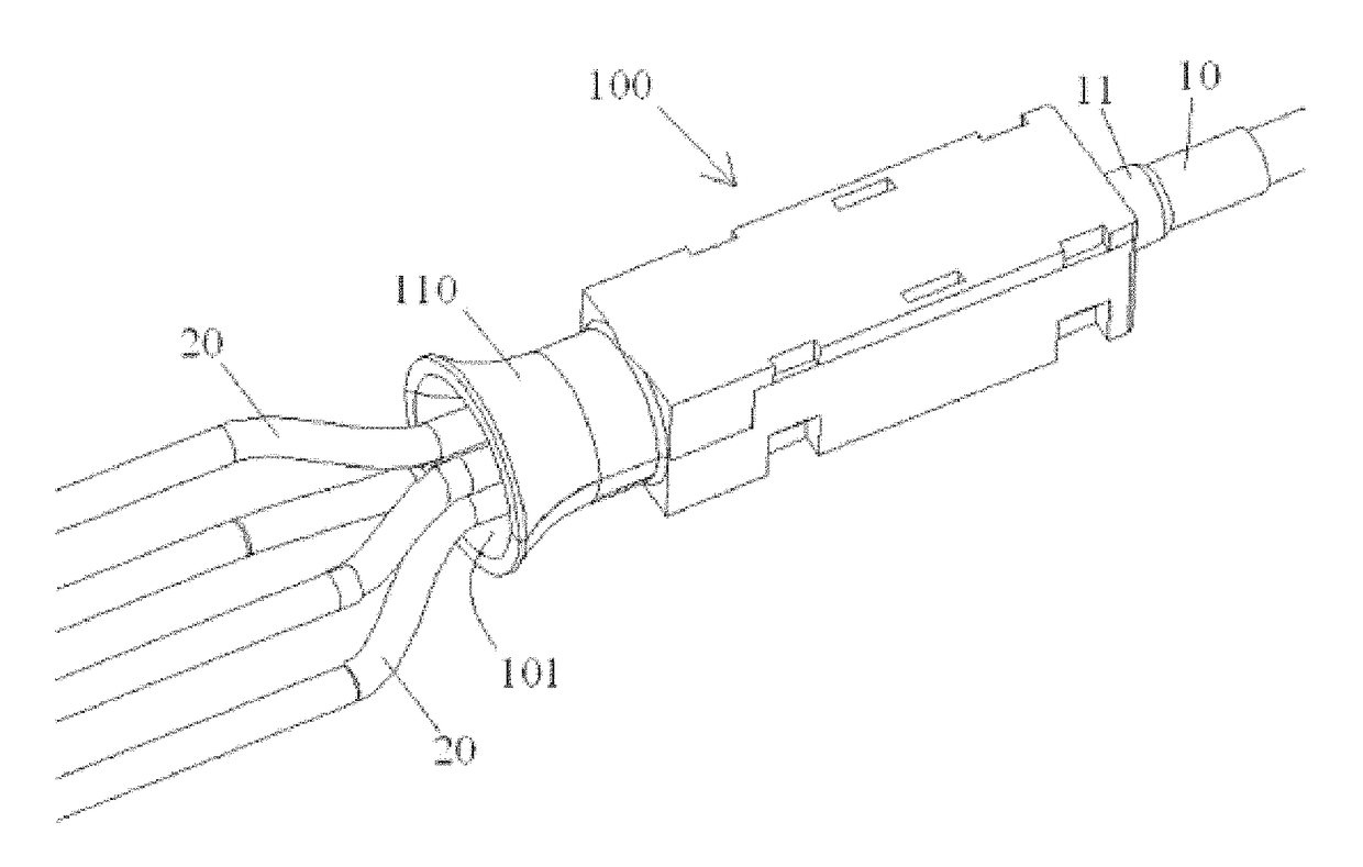
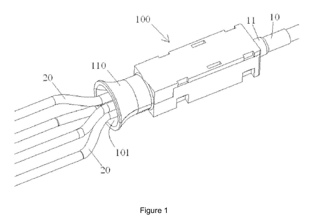
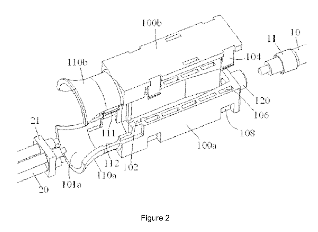
The present invention relates to a device for protecting optical cables, which can be easily manufactured and prevent damage caused by lateral tension without increasing the cost. The device includes a branch cable protective component with a trumpet shaped opening that allows the plurality of branch optical cables to be smoothly bent and stressed along its inner surface without excessive bending. This results in effective prevention of damage to the optical cables from lateral tension. The device has a simple structure and is easy to manufacture.

Problems solved by technology

However, in the prior art, when branch optical cables are subjected to lateral tension (tension in a coaxially perpendicular direction to the branch optical cables), the branch optical cables become bent, causing damage to them, affecting the transmission of the optical signal, and in severe cases, results in interruption of the optical signal.
Although the rubber tail sleeve is capable of protecting the branch optical cables, increasing the stability of the optical signal, it also results in increased costs.

Method used


Image

  • Optical cable fanout device
  • Optical cable fanout device
  • Optical cable fanout device

Examples


Embodiment Construction

[0025]The following implementations, taken in conjunction with the appended diagrams, provide a more detailed description of the technical schemes of the present invention. Within the Description, numbering that is the same or similar occurring in the appended diagrams refers to components that are the same or similar. The aim of the following description of the modes of implementation of the present invention taken in conjunction with the appended diagrams are to aid in interpretation of the overall conceptual framework of the present invention, and should not be understood as restricting the invention in any way.

[0026]Furthermore, in the following detailed descriptions, for convenience of interpretation, many specific details are provided in order to allow a full understanding of the implementations disclosed. It should be clear that, one or more implementations would be possible without these specific details. In all other cases, structures and apparatus which are common knowledg...


PUM


Abstract

The present invention discloses an optical cable fan-out device, used for dividing a single main optical cable into a plurality of branch optical cables. Wherein said optical cable fan-out device comprises of housing, said housing possessing a first end, and a second end opposite said first end. Said main optical cable is introduced into said housing via said first end, and said plurality of branch optical cables are led out from said second end of said housing. Wherein, a branch cable protective component is provided on the second end of said housing, said branch cable protective component possessing a trumpet shaped opening that widens gradually outwards, said plurality of branch optical cables being led out to the exterior of said housing via said trumpet shaped opening. In the present invention, when the branch optical cables are subjected to a lateral tension, the branch optical cables come into contact with the arc-shaped inner surface of the trumpet shaped opening and are uniformly stressed and smoothly bent along the arc-shaped inner surface, without excessive bending occurring; the outcome of this is that, it is possible to effectively prevent damage to the branch optical cables due to lateral tension, without increasing the cost of the optical cable fan-out device.

Description

[0001]The present application asserts a claim on the rights claimed in Chinese patent application 201520009100.0 submitted to the State Intellectual Property Office of the People's Republic of China on 7 Jan. 2015, the full content disclosed in that application being incorporated in quoted form in this document.TECHNICAL FIELD[0002]The present invention relates to an optical cable fan-out device used for dividing a single main optical cable into a plurality of branch optical cables.PRIOR ART[0003]According to the prior art, when it is necessary to split a single multi-core main optical cable into a plurality of branch optical cables, an optical cable fan-out device or optical cable splitter is required. The main optical cable is introduced into the optical cable fan-out device from one end, and a plurality of branch optical cables led out from the other end of the optical cable fan-out device.[0004]However, in the prior art, when branch optical cables are subjected to lateral tensio...

Claims


Application Information

Patent Timeline
Patent Type & Authority Applications(United States)
IPC IPC(8): G02B6/44
CPCG02B6/4476G02B6/4471G02B6/4478G02B6/4477G02B6/44715G02B6/44
Inventor WANG, ZHENGBINCAI, ZHAOHUILIU, YANXU, DONG
Owner COMMSCOPE TELECOMM (SHANGHAI) CO LTD
Why Eureka
Eureka Blog
Learn More