Hemming machine with dual ball screw drive

a technology of ball screw drive and hemmer, which is applied in the direction of metal working apparatus, metal-working apparatus, manufacturing tools, etc., can solve the problems of causing workplace hazards, hydraulic actuators were required to displace, and previously known hemmer machines, etc., to achieve accurate hemmer operation, reduce overall hemmer height, and sufficient rigidity

Inactive Publication Date: 2002-11-05
VALIANT CO LTD
View PDF9 Cites 18 Cited by
  • Summary
  • Abstract
  • Description
  • Claims
  • Application Information

AI Technical Summary

Benefits of technology

The cradle is preferably formed by a spaced apart beam assembly having a connected portion at each end. The ball screws are threadably connected with the connected portion at each end of the cradle. This construction for the cradle thus minimizes the overall hemmer height, as well as the cradle weight and thus the required output from the drive motor while still maintaining sufficient rigidity to accurately perform the hemming operation.

Problems solved by technology

There have, however, been a number of disadvantages of these previously known hemming machines.
A primary disadvantage is that the hydraulic actuators were required to displace the nest with its supported part between the prehem and final hem positions.
Such hydraulic actuators, however, are prone to leakage and thus create workplace hazards.
A still further disadvantage of these previously known hemming machines is that, in the event that the nest and / or base deflects during the operation of the hemming machine, accurate positioning of the hemming tooling with respect to the nest is difficult to maintain.
Unless the hemming tooling is accurately positioned relative to the nest, inaccuracies in the hemmed part will result.

Method used


Image

  • Hemming machine with dual ball screw drive
  • Hemming machine with dual ball screw drive
  • Hemming machine with dual ball screw drive

Examples


Embodiment Construction

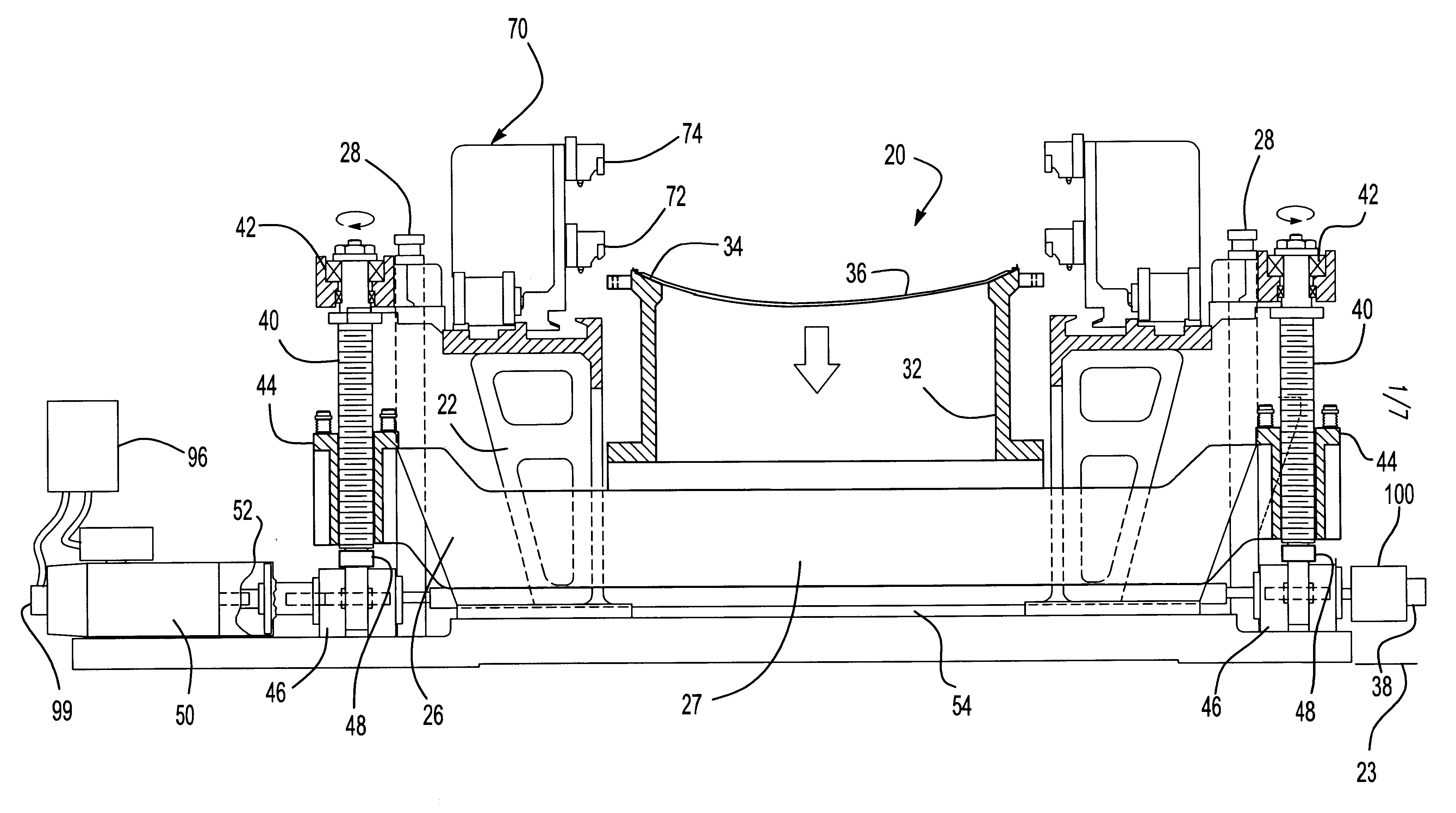
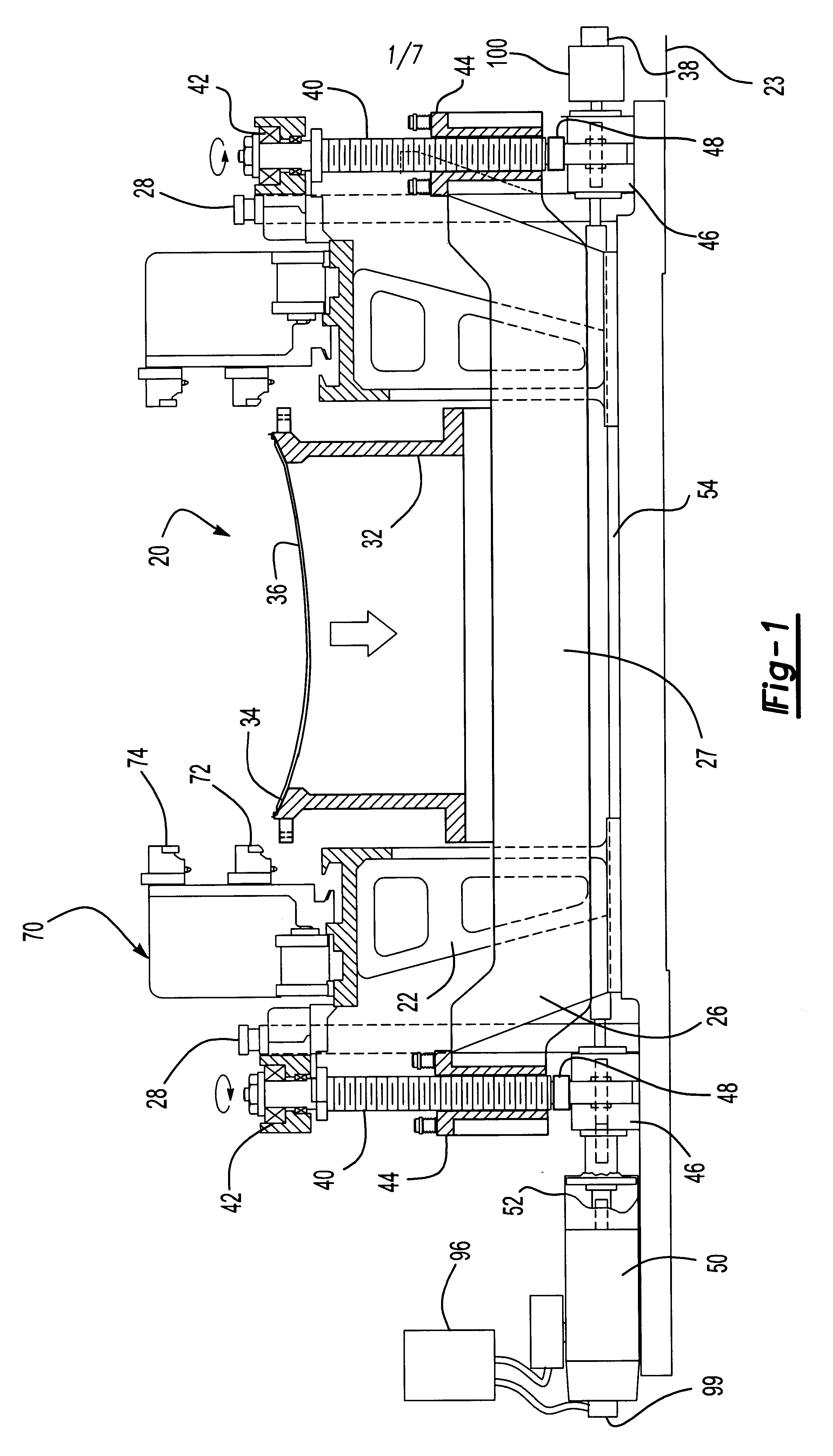
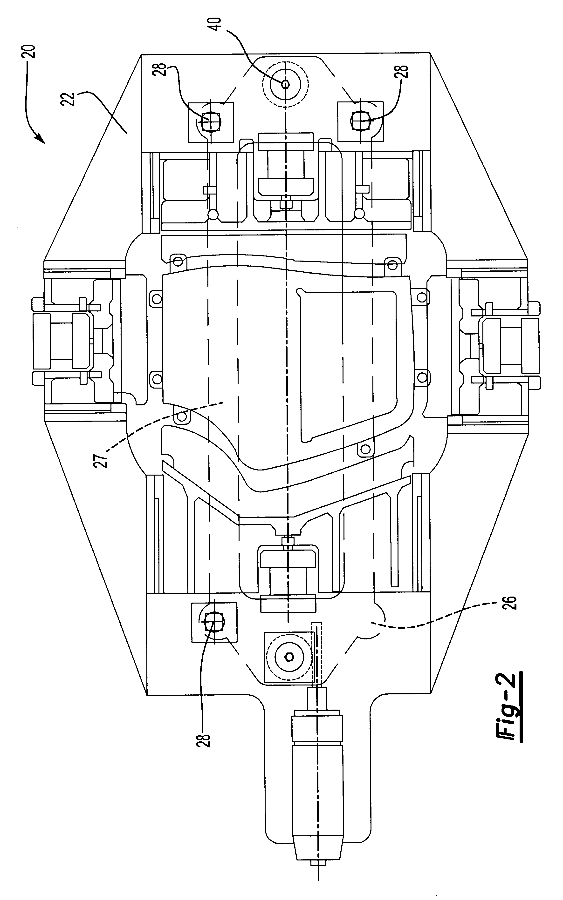
With reference first to FIGS. 1 and 2, a preferred embodiment of the hemming machine 20 of the present invention is there shown. The hemming machine 20 includes a stationary base 22 which is supported on a ground support surface 23 (FIG. 1).

A cradle 26 is vertically slidably mounted to the base 22 such that the cradle 26 is vertically movable relative to the base 22. A plurality of guide rods 28 are secured to the base 22 and extend through appropriate openings in the cradle 26 to guide the cradle 26 as the cradle 26 vertically moves relative to the base 22.

As best shown in FIG. 2, the cradle 26 preferably comprises a pair of spaced apart beams 27 having a connected portion 30 at each end of the beams 28. The beams 27 are preferably steel I beams with additional cross supports to rigidify the cradle 26.

With reference again to FIG. 1, a nest 32 is secured to the cradle 26 so that the nest 32 moves in unison with the cradle 26. The nest 32 includes an upper surface 34 configured to su...


PUM

PropertyMeasurementUnit
rotationaaaaaaaaaa
speedaaaaaaaaaa
vertical movementaaaaaaaaaa

Abstract

A hemming machine for sheet metal is disclosed having a base adapted to be supported on a ground support surface. A cradle is vertically slidably mounted to the base while a nest is mounted to the cradle and adapted to support the part to be hemmed. Hemming tooling is mounted to the base and movable between an extended position in which the hemming tooling overlies the nest, and a retracted position in which the hemming tooling is spaced laterally outwardly from the nest. A pair of spaced ball screws are rotatably mounted to the base and threadably connected to the cradle on opposite sides of the nest so that rotation of the ball screws vertically displaces the cradle relative to the base. A single drive motor is drivingly connected through a two speed gear box to both ball screws to rotatably drive the ball screws in synchronism with each other.

Description

I. Field of the InventionThe present invention relates generally to a hemming machine for sheet metal.II. Description of the Prior ArtThere are many previously known hemming machines for producing a sheet metal hem between two parts. Such hemming machines are frequently employed in the automotive industry as well as other industries.These previously known hemming machines typically comprise a stationary base having a nest vertically slidably mounted to the base. The nest is dimensioned to support the part to be hemmed while actuators, typically hydraulic actuators, vertically displace the nest with its supported part.In order to perform the hem, hemming tooling is mounted to the base and movable between an extended position and a retracted position. In its extended position, the hemming tooling overlies the nest while, conversely, in its retracted position, the hemming tooling is spaced laterally outwardly from the nest to allow the part as well as the nest to move vertically past t...

Claims


Application Information

Patent Timeline
Patent Type & Authority Patents(United States)
IPC IPC(8): B21D39/02
CPCB21D39/021Y10T29/53791
Inventor DENIS, KENNETH SAINTCOTE, RAYRAFFIN, LOUISHARRISON, LEE
Owner VALIANT CO LTD
Why Eureka
Try Eureka