Compressor having counter-weight cup

a compressor and weight cup technology, applied in the direction of machines/engines, rotary/oscillating piston pump components, liquid fuel engines, etc., can solve the problems of limited rotational movement of the shield member relative to the bearing assembly, increased power consumption, and increased power consumption, so as to reduce the overall height of the housing, and reduce the effect of overall heigh

Inactive Publication Date: 2008-03-20
EMERSON CLIMATE TECH INC
View PDF11 Cites 17 Cited by
  • Summary
  • Abstract
  • Description
  • Claims
  • Application Information

AI Technical Summary

Benefits of technology

[0002]Typical refrigeration compressors incorporate a lubricant sump in the lower or bottom portion of the housing into which the drive shaft extends so as to pump lubricant therefrom to the various portions requiring lubrication. In addition, the lubricant also often acts to aid in removal of heat from the various components. In order to ensure sufficient lubricant is contained within the sump to assure adequate lubrication and / or cooling of the moving parts while also minimizing the overall height of the housing, it is sometimes necessary that the lubricant level extend above the rotating lower end of the rotor and the counter weight thereon. However, the higher viscosity of the lubricant as compared to refrigerant and gas creates an increased drag on rotation of the rotor, resulting in increased power consumption. This problem may be further aggravated in scroll-type compressors, which typically employ a counter weight secured to the lower end of the rotor.
[0003]A shield for a refrigeration compressor that advantageously limits its axial position is disclosed. A portion of the shield may engage with a bearing assembly such that axial movement of the shield member relative to the bearing assembly is limited by the engagement. A portion of the shield member may engage with the bearing assembly such that rotational movement of the shield relative to the bearing assembly is limited by the engagement. Axial and rotational movement of a shield member relative to the shell of the refrigeration compressor may be limited by engagement of the shield member with components other than the shaft. The shield member advantageously restricts lubricant flow to the rotating lower end of the rotor whereby power consumption of the motor is reduced.

Problems solved by technology

However, the higher viscosity of the lubricant as compared to refrigerant and gas creates an increased drag on rotation of the rotor, resulting in increased power consumption.
This problem may be further aggravated in scroll-type compressors, which typically employ a counter weight secured to the lower end of the rotor.
A portion of the shield may engage with a bearing assembly such that axial movement of the shield member relative to the bearing assembly is limited by the engagement.
A portion of the shield member may engage with the bearing assembly such that rotational movement of the shield relative to the bearing assembly is limited by the engagement.
Axial and rotational movement of a shield member relative to the shell of the refrigeration compressor may be limited by engagement of the shield member with components other than the shaft.

Method used


Image

  • Compressor having counter-weight cup
  • Compressor having counter-weight cup
  • Compressor having counter-weight cup

Examples


Embodiment Construction

[0018]The following description is merely exemplary in nature and is in no way intended to limit the teachings, its application, or uses.

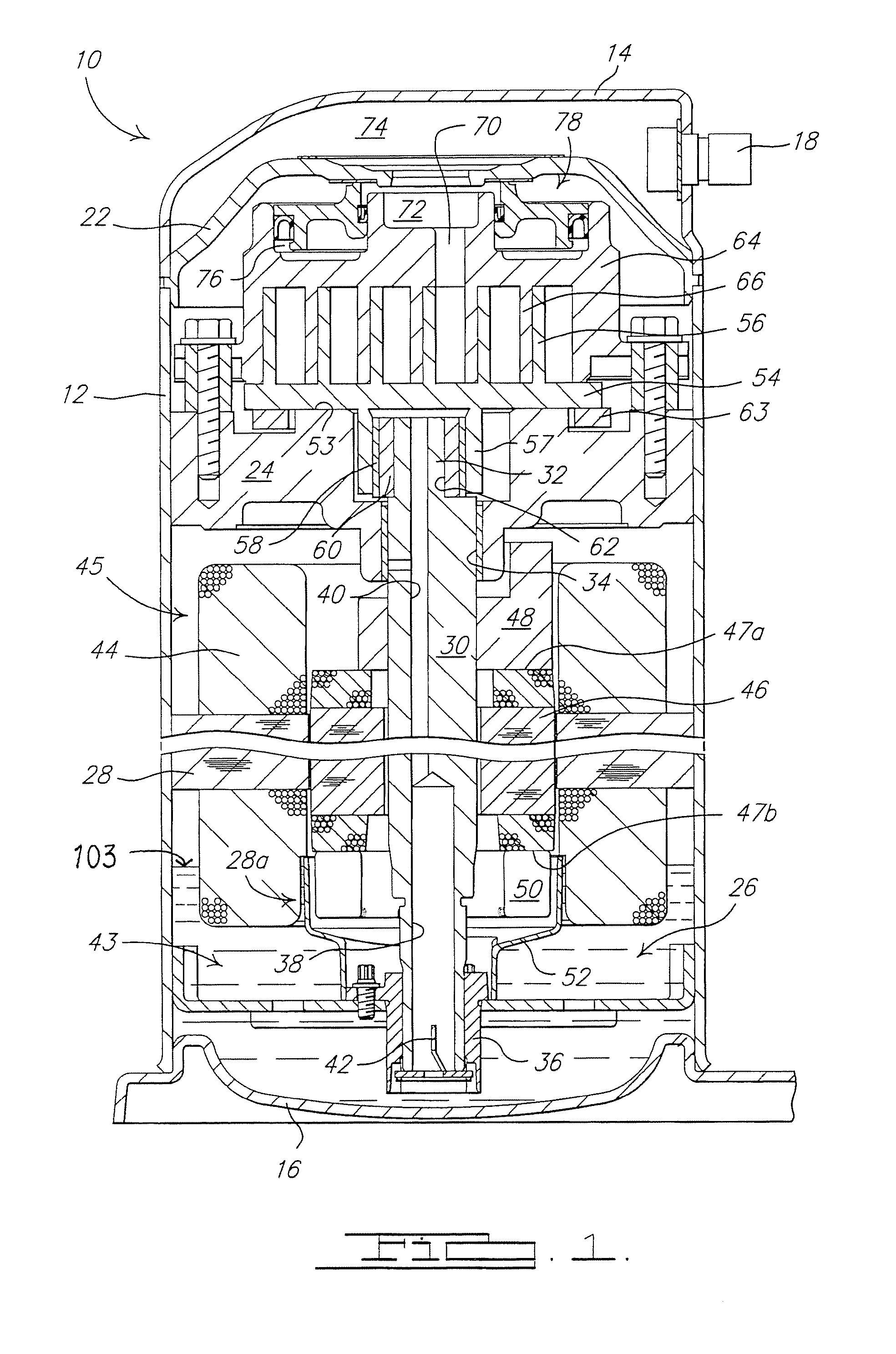
[0019]Referring now to the drawings and in particular to FIG. 1, a compressor 10 includes a generally cylindrical hermetic shell 12 having welded at the upper end thereof a cap 14 and at the lower end thereof a base 16 having a plurality of mounting feet (not shown) integrally formed therewith. Cap 14 is provided with a refrigerant discharge fitting 18 which may have the usual discharge valve therein (not shown). A transversely extending partition 22 is welded about its periphery at the same point that cap 14 is welded to shell 12. A stationary main bearing housing or body 24 and a lower bearing assembly 26 are secured to shell 12. A motor stator 28, which is generally square in cross section but with the corners rounded off, is press-fit into shell 12. The flats between the rounded corners on the stator 28 provide passageways between stator 28 and...


PUM


Abstract

A cup-shaped shield surrounds a counter weight on the lower end of a rotor of the refrigeration compressor. The shield advantageously restricts lubricant flow to the rotating lower end of the rotor whereby power consumption of the motor is reduced. The shield may be axially and / or rotationally limited by engagement with a lower bearing assembly. The shield may be used on a scroll compressor. The shield may also be used on a rotor without having a counter weight on the lower end thereof.

Description

BACKGROUND AND SUMMARY[0001]The present teachings relate generally to field compressors and, more specifically, to lubrication systems for compressors.[0002]Typical refrigeration compressors incorporate a lubricant sump in the lower or bottom portion of the housing into which the drive shaft extends so as to pump lubricant therefrom to the various portions requiring lubrication. In addition, the lubricant also often acts to aid in removal of heat from the various components. In order to ensure sufficient lubricant is contained within the sump to assure adequate lubrication and / or cooling of the moving parts while also minimizing the overall height of the housing, it is sometimes necessary that the lubricant level extend above the rotating lower end of the rotor and the counter weight thereon. However, the higher viscosity of the lubricant as compared to refrigerant and gas creates an increased drag on rotation of the rotor, resulting in increased power consumption. This problem may ...

Claims


Application Information

Patent Timeline
Patent Type & Authority Applications(United States)
IPC IPC(8): F01C1/02F01C1/063
CPCF04C18/0215F04C23/008F04C2240/809F04C2240/50F04C29/02
Inventor BONIFAS, MARK A.
Owner EMERSON CLIMATE TECH INC
Why Eureka
Try Eureka