Optical fiber cable and manufacturing method of optical fiber cable

A fiber optic cable and fiber optic cable technology, which is applied in the field of fiber optic cable and fiber optic cable manufacturing, can solve the problems of weak connection ability of the protective sleeve, damage of the fiber optic cable, and difficulty in erecting the staff.

Inactive Publication Date: 2020-07-07
淮南市明理网络科技有限公司
View PDF1 Cites 2 Cited by
  • Summary
  • Abstract
  • Description
  • Claims
  • Application Information

AI Technical Summary

Problems solved by technology
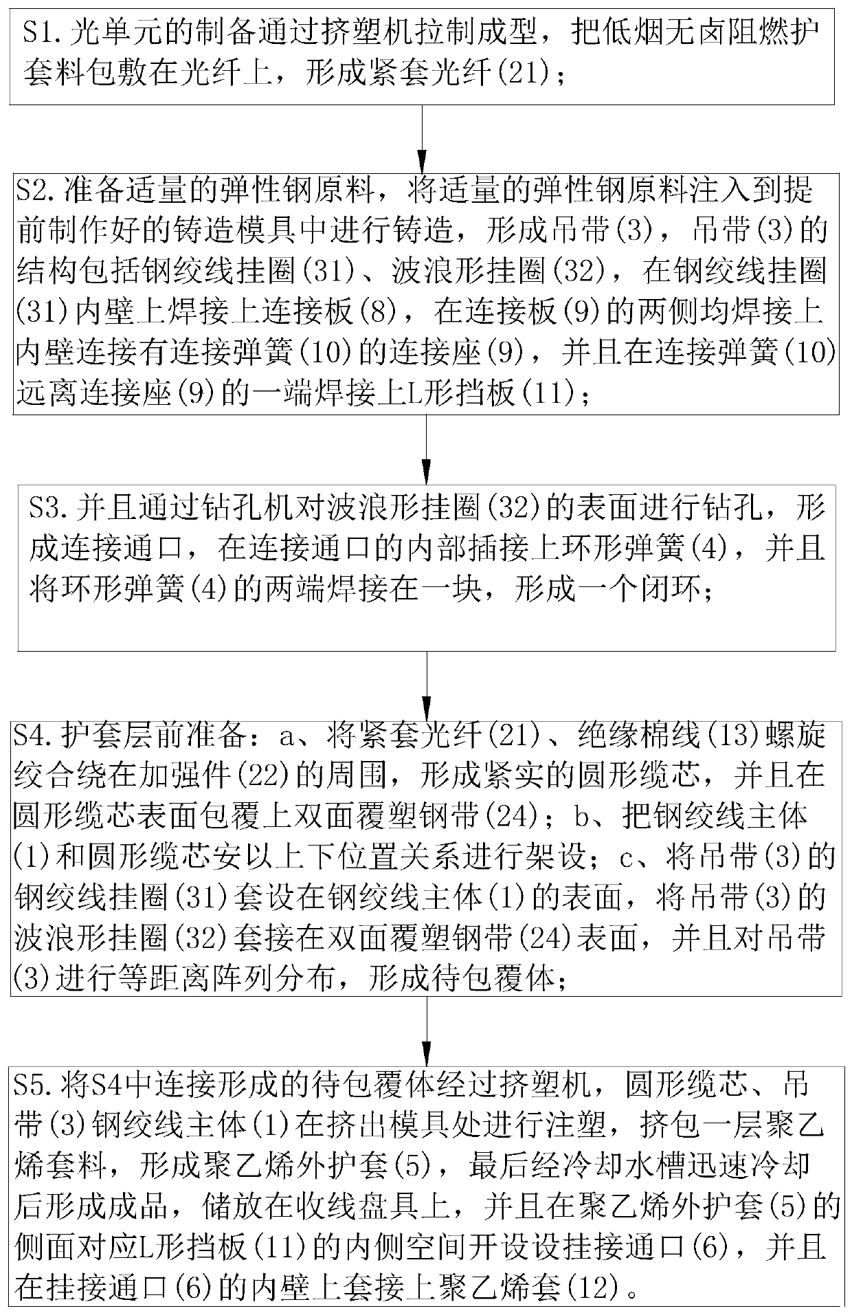
[0004] In the prior art, when erecting a self-supporting optical cable, it is necessary to hang the optical fiber cable between two utility poles, and the wind and rain will cause a large pulling force on the optical fiber cable. The connection with the optical cable part is only carried out by the protective sheath wrapped outside, so that the steel strand and the optical cable part support each other, and the connection ability of the protective sheath is weak. Separation will cause damage to the fiber optic cable, and when the self-supporting fiber optic cable is required to be connected to the utility pole, there is a lack of stress points, which increases the difficulty of erection by the staff

Method used


Image

  • Optical fiber cable and manufacturing method of optical fiber cable
  • Optical fiber cable and manufacturing method of optical fiber cable
  • Optical fiber cable and manufacturing method of optical fiber cable

Examples


Embodiment approach

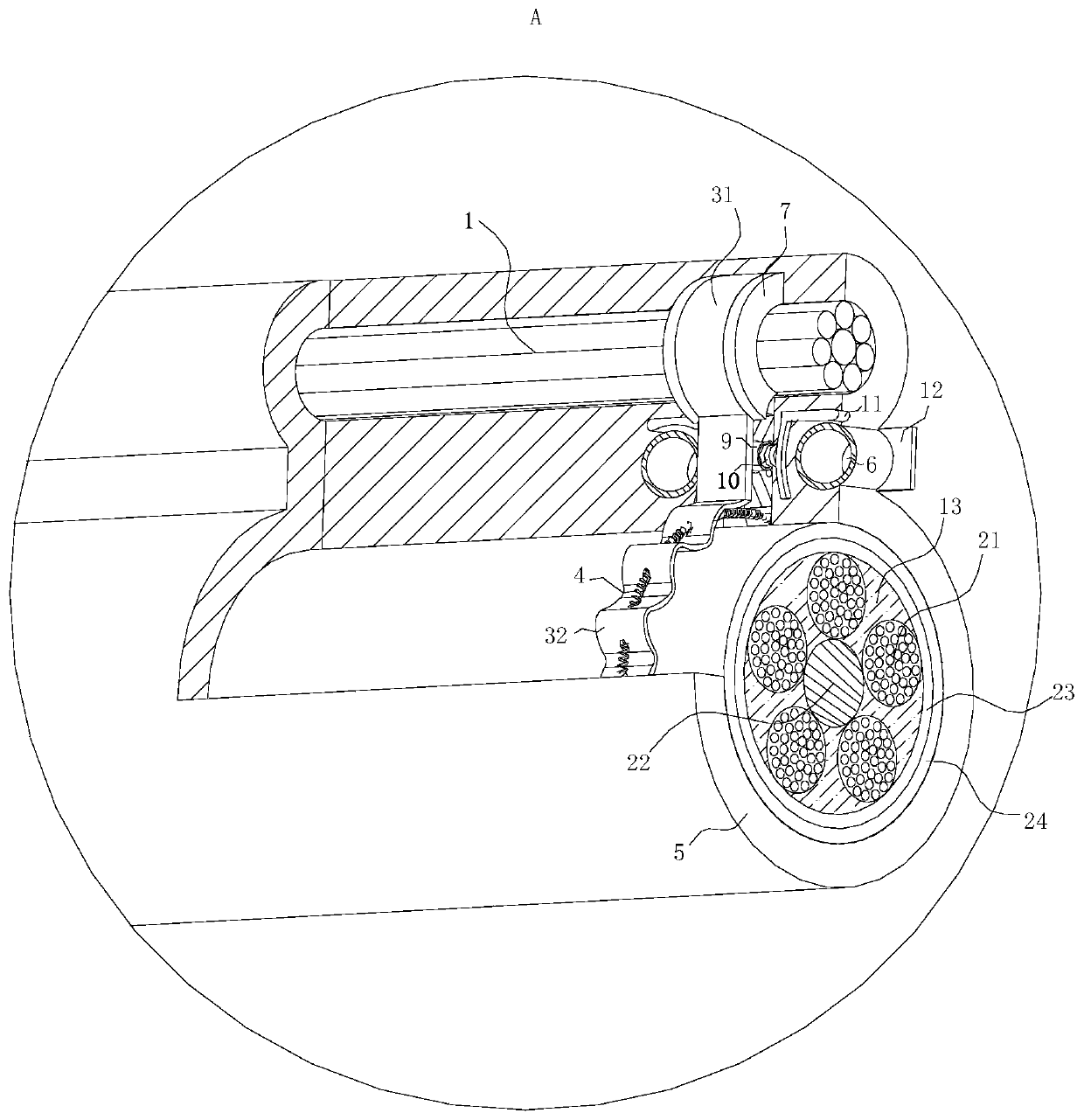
[0033] As an embodiment of the present invention, a connecting plate 8 is fixedly connected to the inner wall of the steel strand hanging ring 31 ; both sides of the connecting plate 8 are fixedly connected with a connecting seat 9 ; A connection spring 10 is fixedly connected on the upper part; when working, when the hooking rope is attached to the hooking port 6, when the wind and rain are hit and the optical fiber cable is shaking, the hooking rope is connected to the inner side of the hooking port 6. The force is large, and it is easy to produce a squeezing force on the side of the sling 3, which adds a larger driving force to the sling 3 and affects the stability of the sling 3. By setting the connecting seat 9 and the connecting spring 10, the side of the sling 3 can be increased. The supporting point, when the side receives the extrusion force, the connecting spring 10 will elastically expand and contract, which can buffer the extrusion force, reduce the extrusion of the...


PUM


Abstract

The invention belongs to the technical field of optical fiber cables, and particularly relates to an optical fiber cable and a manufacturing method of the optical fiber cable. The optical fiber cablecomprises a steel strand main body and an optical cable part, wherein the steel strand main body and the optical cable part are connected through a hanging belt. According to the invention, the hanging belt, a steel strand hanging ring, a wavy hanging ring, an annular spring and a hanging connection port are arranged; when a polyethylene outer sheath of the optical fiber cable cracks, the steel strand main body can be prevented from being separated from the optical cable part under the action of the hanging belt, and the pulling of the optical cable part to the steel strand main body is buffered under the mutual cooperation of the wavy hanging ring and the annular spring, so that the self-supporting capacity is indirectly improved, and the problem of damage to the optical fiber cable is avoided; and by arranging the hanging connection port, when the surface of the optical fiber cable is connected and fixed, a hanging connection acting point can be provided through the hanging connection port, a worker can conveniently hang the optical fiber cable, and the erection difficulty is reduced.

Description

technical field [0001] The invention belongs to the technical field of optical fiber cables, in particular to an optical fiber cable and a manufacturing method of the optical fiber cable. Background technique [0002] Aerial optical cables are optical cables that are hung on poles. This laying method can make use of the original overhead open line pole road, save construction costs and shorten the construction period. Aerial optical cables are hung on poles and are required to be able to adapt to various natural environments. Aerial optical cables are easily threatened by natural disasters such as typhoons, ice, floods, etc., and are also easily affected by external forces and the weakening of their own mechanical strength. Therefore, the failure rate of overhead optical cables is higher than that of direct buried and pipeline optical fiber cables. [0003] There are also some technical solutions for optical fiber cables in the prior art. For example, a Chinese patent with...

Claims


Application Information

Patent Timeline
Patent Type & Authority Applications(China)
IPC IPC(8): G02B6/44
CPCG02B6/4479G02B6/4486
Inventor 冉肖伟杨君梅
Owner 淮南市明理网络科技有限公司
Why Eureka
Try Eureka