
Camera arrangement for a motor vehicle

A technology for cameras and automobiles, applied in electric heating devices, vehicle cleaning, transparent/reflective heating devices, etc., can solve problems such as large installation space

Inactive Publication Date: 2009-03-04
LEOPOLD KOSTAL GMBH & CO KG
View PDF1 Cites 12 Cited by
  • Summary
  • Abstract
  • Description
  • Claims
  • Application Information

AI Technical Summary

Problems solved by technology

However, since an optical sensor is provided in addition to an electric sensor, there is still a problem that a large installation space is required

Method used


Image

  • Camera arrangement for a motor vehicle
  • Camera arrangement for a motor vehicle

Examples


Embodiment Construction

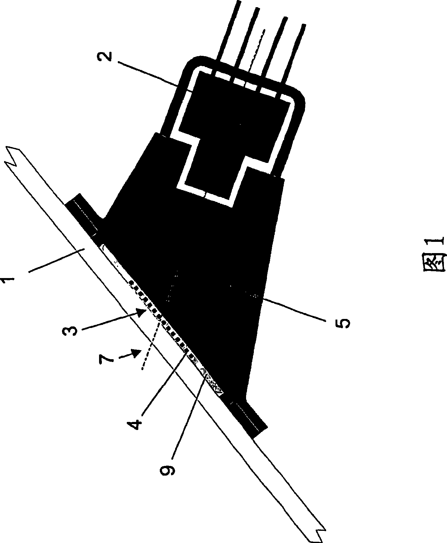
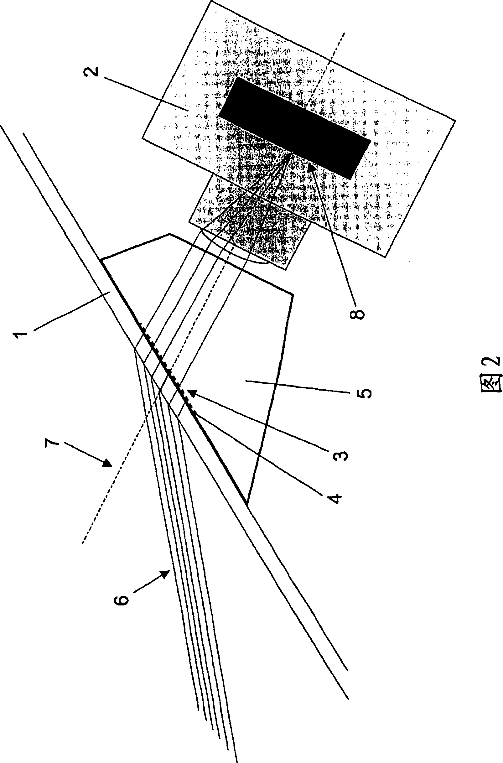
[0022] FIG. 1 shows a motor vehicle glazing (1), in particular a windshield of a motor vehicle, to which the outer surface of an optical waveguide (5) is coupled on its inner side. The section of the light guide (5) opposite this plane is connected to the camera (2). Preferably, in a manner not shown here, a part of the light guide ( 5 ) can integrally form part of the camera optics.

[0023] The light guide (5) is made of a material having the same or a similar refractive index as the car glass (1) and thus makes it possible to achieve almost no refraction from the car glass (1) to the light guide (5) and to the camera (2) The optical path (Strahlengang). The light guide ( 5 ), which is only schematically shown here, can be formed by a fixed prism body or else by a lens tube filled with optically transparent material. Preferably, in each case, in order to avoid stray light influences, the sides of the light guide ( 5 ) are rendered light-impermeable, for example by being dy...


PUM


Abstract

The invention relates to a camera arrangement for a motor vehicle, comprising a camera (2) which is oriented towards a vehicle window, and at least one electric conductor structure (3) which is directly or indirectly connected to a vehicle window (1). Said conductor structure is arranged in the detection range of the camera (2).

Description

technical field [0001] The invention relates to a camera arrangement for a motor vehicle with a camera aimed at the vehicle window and at least one electrical conductor structure, wherein the electrical conductor structure is directly or indirectly connected to the vehicle window. Background technique [0002] A large number of sensors are used in modern motor vehicles, which have to find an installation place on the window pane, more precisely mostly especially on the windshield, in order to acquire information from the vehicle exterior. This is especially true for camera systems that capture images. However, rain sensors, moisture sensors (Beschlags sensors) and other optical sensors, such as sunlight or ambient light sensors, are mostly also mounted on the windshield. [0003] German patent application DE 10340901 A1 discloses a roof module for a motor vehicle, wherein a specific embodiment of the module includes a camera. Furthermore, the top module also includes at le...

Claims


Application Information

Patent Timeline
Patent Type & Authority Applications(China)
IPC IPC(8): B60R11/04B60S1/08H01Q1/32H04N5/247H05B3/84G02B7/00H04N23/90
CPCB60S1/0825H05B2203/017H05B3/84H01Q1/1271B60S1/0844B60S1/0837B60R2011/0026B60S1/0822H01Q1/325H01Q1/3233B60S1/0862G06V20/56
Inventor F·布莱辛R·博贝尔G·贝尼M·里奇温T·韦伯
Owner LEOPOLD KOSTAL GMBH & CO KG
Features
  • Generate Ideas
  • Intellectual Property
  • Life Sciences
  • Materials
  • Tech Scout
  • Unparalleled Data Quality
  • Higher Quality Content
  • 60% Fewer Hallucinations
Learn More