Winding machine

A technology of winding machine and bobbin, which is applied in the field of winding machine to achieve the effect of enhancing the rigidity of the bracket

Inactive Publication Date: 2009-03-04
OERLIKON TEXTILE GMBH & CO KG
View PDF1 Cites 12 Cited by
  • Summary
  • Abstract
  • Description
  • Claims
  • Application Information

AI Technical Summary

Problems solved by technology

[0006] Another disadvantage due to the increased structural lengt...

Method used


Image

  • Winding machine
  • Winding machine
  • Winding machine

Examples


Embodiment Construction

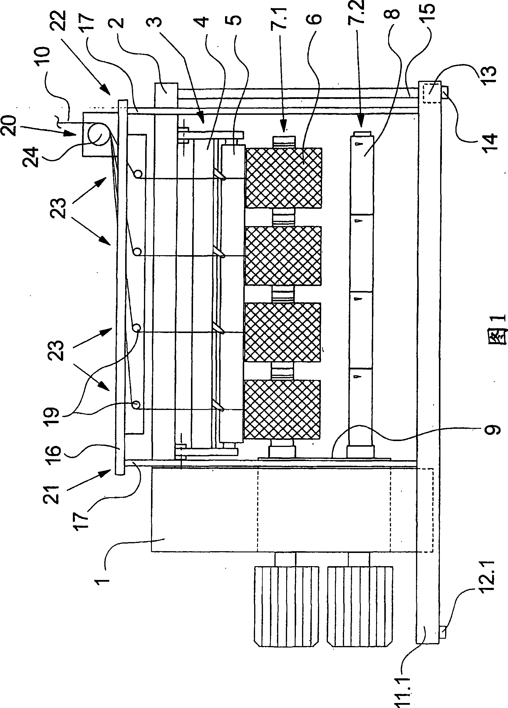
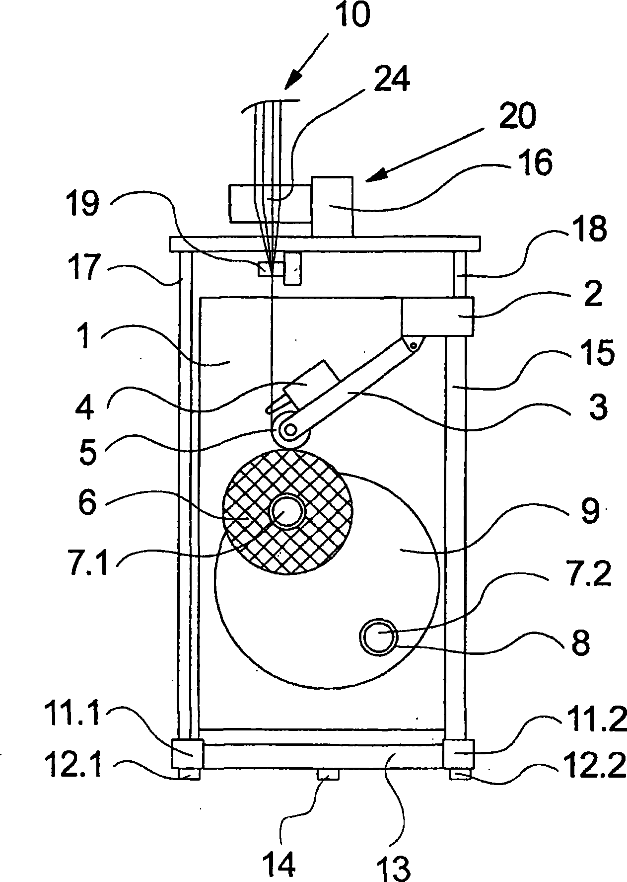
[0026] FIG. 1 shows a side view of a first embodiment of a winding machine according to the invention. figure 2 A front view of the same winder is shown. The following description refers to these two figures.

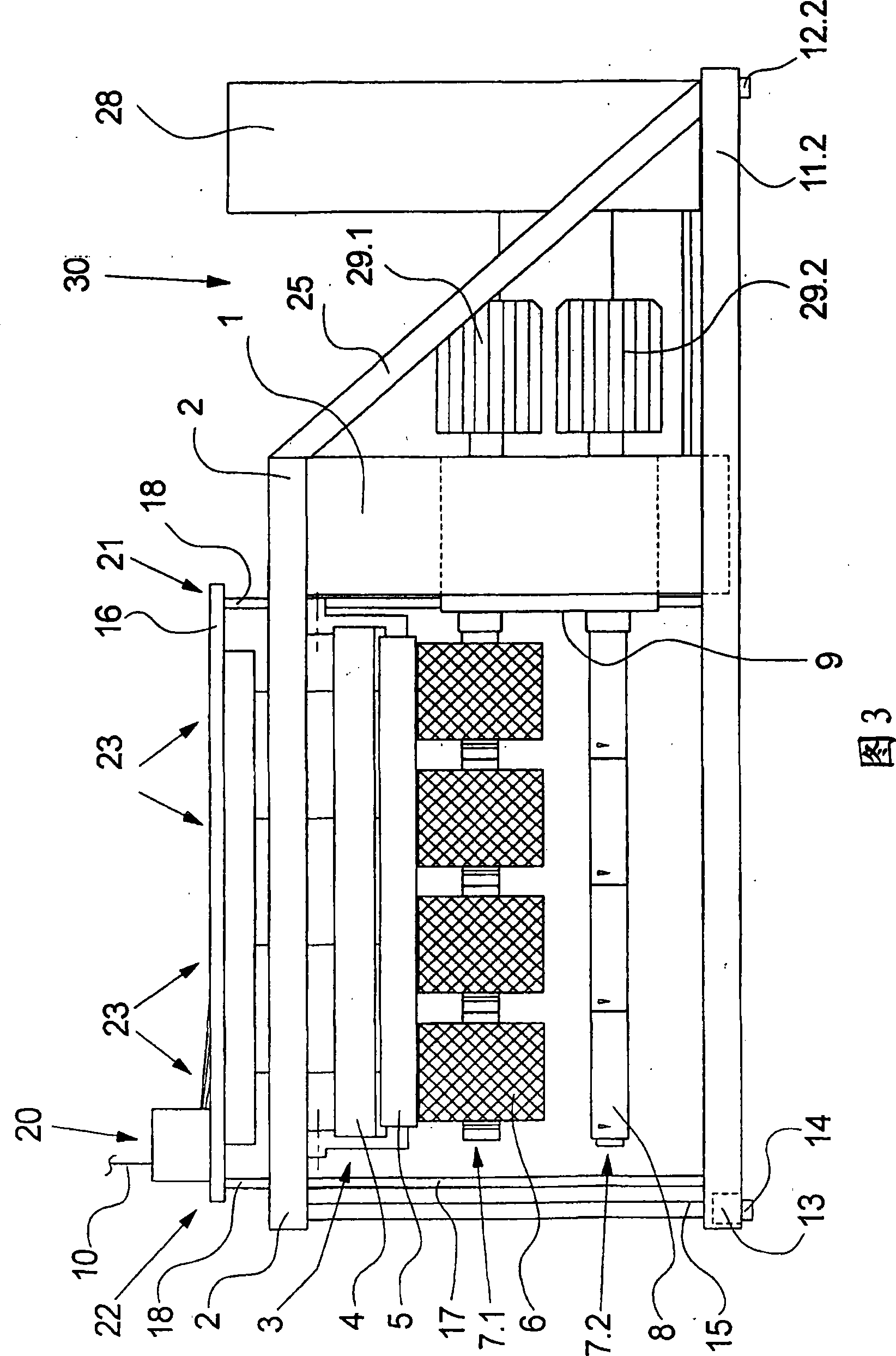
[0027] The housing 1 of the winding machine supports a rotatable turntable 9 in which two bobbin spindles 7.1, 7.2 and their drives are rotatably mounted. By rotating the turntable 9, the bobbin spindles 7.1, 7.2 can be swiveled alternately into a lower changing area and an upper winding area. In the winding area, a pressure roller 5 is arranged above the bobbin spindle 7.1. Turntable 9 is at the same time the device by which the distance between pressure roller 5 and winding spindle 7.1 increases as the diameter of the package increases.

[0028] In the winding machine shown here, four winding heads 23 and four bobbins 6 are shown to simplify the illustration. This is typical for one or for a greater number of winding heads. Especially in the bobbin spindles with ...


PUM


Abstract

The invention relates to a winding machine for winding a plurality of continuously fed threads (10) onto bobbins (6), having winding spindles (7.1, 7.2) which are mounted on a housing side (21) on one side and having a substantially stationary thread transfer device (3). The thread transfer device is held by a carrier (2) which extends from the housing side (21) as far as a cantilevered side (22) and is supported on the housing (1). In order to improve the static and dynamic rigidity of the cantilevered carrier of the thread transfer device, said carrier is supported vertically according to the invention at its cantilevered end on the cantilevered side.

Description

technical field [0001] The invention relates to a winder according to the preamble of claim 1 . Background technique [0002] The winder is used to wind the continuously fed yarn into bobbins. A winding machine of this type is known from the laid-open document DE 103 14 293 A1. For winding, the yarn is first reciprocated by a traversing device transversely to the direction of yarn flow and guided via a rotating pressure roller. Pressure rollers place the yarns individually on the same rotating bobbin to be wound. Here a plurality of bobbins are aligned one behind the other on a common bobbin spindle. This allows multiple yarns to be wound simultaneously. [0003] Full bobbins and empty bobbins are exchanged axially from the bobbin spindles or onto the bobbin spindles. For this purpose, the bobbin spindle is mounted cantilevered at one end. Likewise, the pressure roller and the traversing device combined into an anti-overlapping device are fixed on a cantilever beam typ...

Claims


Application Information

Patent Timeline
IPC IPC(8): B65H54/72B65H67/048
CPCB65H54/72B65H2701/31B65H67/048
Inventor M·施勒特尔
Owner OERLIKON TEXTILE GMBH & CO KG
Why Eureka
Try Eureka