Coin receiving/dispensing machine

A coin and coin machine technology, applied in the direction of coin counting, handling coins or valuable banknotes, coin-free or similar appliances, etc., can solve problems such as being unsuitable for cash collection and change machines, and achieve reduction in size and increase in coins. The effect of compact storage capacity and conveying mechanism

A coin and coin machine technology, applied in the direction of coin counting, handling coins or valuable banknotes, coin-free or similar appliances, etc., can solve problems such as being unsuitable for cash collection and change machines, and achieve reduction in size and increase in coins. The effect of compact storage capacity and conveying mechanism

CN101379531AActive Publication Date: 2009-03-04GLORY KOGYO KK

Image

  • Coin receiving/dispensing machine
  • Coin receiving/dispensing machine
  • Coin receiving/dispensing machine

Examples


Embodiment Construction

[0048] One embodiment of the present invention will be described below with reference to the drawings.

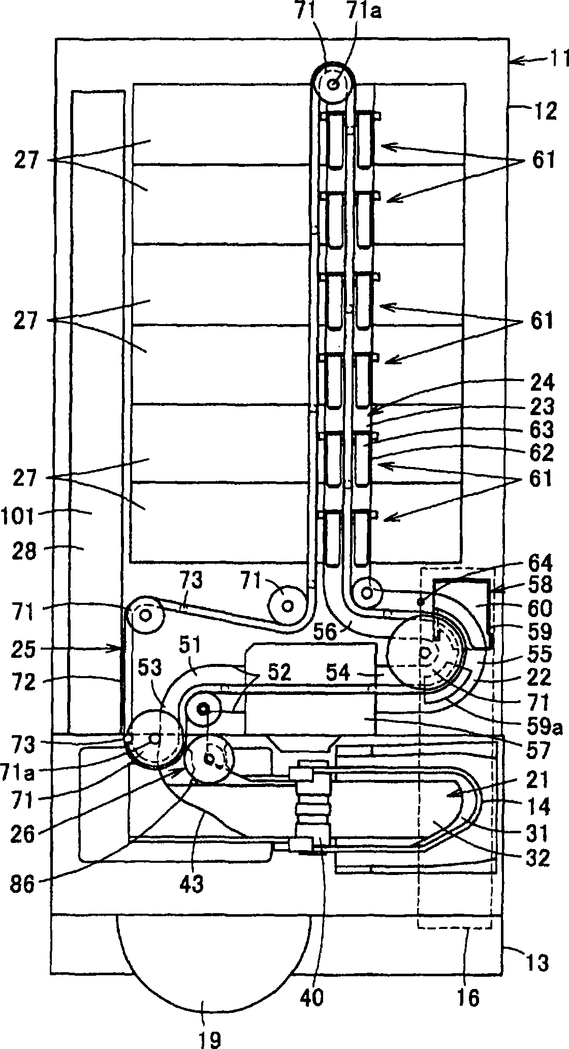
[0049] Figure 7 The perspective view of the coin deposit and dispensing machine is shown in . The coin dispenser is, for example, a coin dispenser that is electrically connected to a POS cash register unit in a cash register at a store, and can automatically receive and dispense coins.

[0050] The body 11 of the coin deposit and withdrawal machine includes a frame body 12 with an open front surface and a main body unit 13 that can be pulled out from the front surface of the frame body 12 . The dimension along the body width direction of the front surface of the body 11 is formed to be approximately half the width of the POS cash register, and can be used in combination with a banknote deposit and dispense machine having the same width as the coin dispenser.

[0051] On the upper surface of the front part of the main body unit 13 protruding from the frame body 12 of the ...


PUM


Abstract

A coin receiving / dispensing machine where an increased number of coins can be received. This is achieved by reducing that space above a passage which is required for coin conveyance, reducing the size of a machine body (11), and allocating the reduced space for a receiving / discharge section (27). An endless conveyance belt (72) is stretched over an identification path (22) and a classification path (23) by pulleys (71) horizontally rotatably supported by vertical shafts (71a). That space above the passage which is required to place the conveyance belt (72) is reduced, the machine body (11) is reduced in size, and the reduced space is allocated for receiving / discharge section (27). All of these contribute to increase the number of coins receivable in the machine.

Description

technical field [0001] The present invention relates to a coin depositing and dispensing machine capable of receiving and dispensing coins. Background technique [0002] In the past, in order to accurately and quickly carry out cash receipts and payments with customers at, for example, cash registers (registers) of stores and windows of financial institutions, etc., such coin deposit and dispense machines have been developed: they are compatible with POS (Point Of Sells: electronic Cash register system) cash registers or electronic cash registers and cash management machines and other cash registers are electrically connected, and according to the electrical signals output from these cash registers, cash income and expenditure can be automatically carried out. [0003] The coin deposit and withdrawal machine has a coin receiving port on the upper front surface of the machine body, which can receive multiple coins at the same time, and a conveyor belt is arranged along the si...

Claims


Application Information

Patent Timeline
04 Mar 2009
Publication
CN101379531A
IPC
G07D13/00; G07D9/04; G07F19/00
Inventors
田中隆志; 千叶真一