
Thread cutting apparatus for sewing machine

A sewing machine and thread trimming technology, which is applied to the sewing machine control device, sewing machine components, and thread cutting mechanism in the sewing machine, etc., can solve the problems such as the broken shape of the upper thread loop, the failure of the thread catching part to protrude and rise, etc.

Inactive Publication Date: 2009-03-11
BROTHER KOGYO KK
View PDF1 Cites 4 Cited by
  • Summary
  • Abstract
  • Description
  • Claims
  • Application Information

AI Technical Summary

Problems solved by technology

Therefore, the shape of the upper thread loop is broken, the area where the tip of the thread catching part can be inserted narrows, and the probability of failure to insert the thread catching part increases.

Method used


Image

  • Thread cutting apparatus for sewing machine
  • Thread cutting apparatus for sewing machine
  • Thread cutting apparatus for sewing machine

Examples


Embodiment Construction

[0048] The present invention will be described in detail below with reference to the drawings showing preferred embodiments.

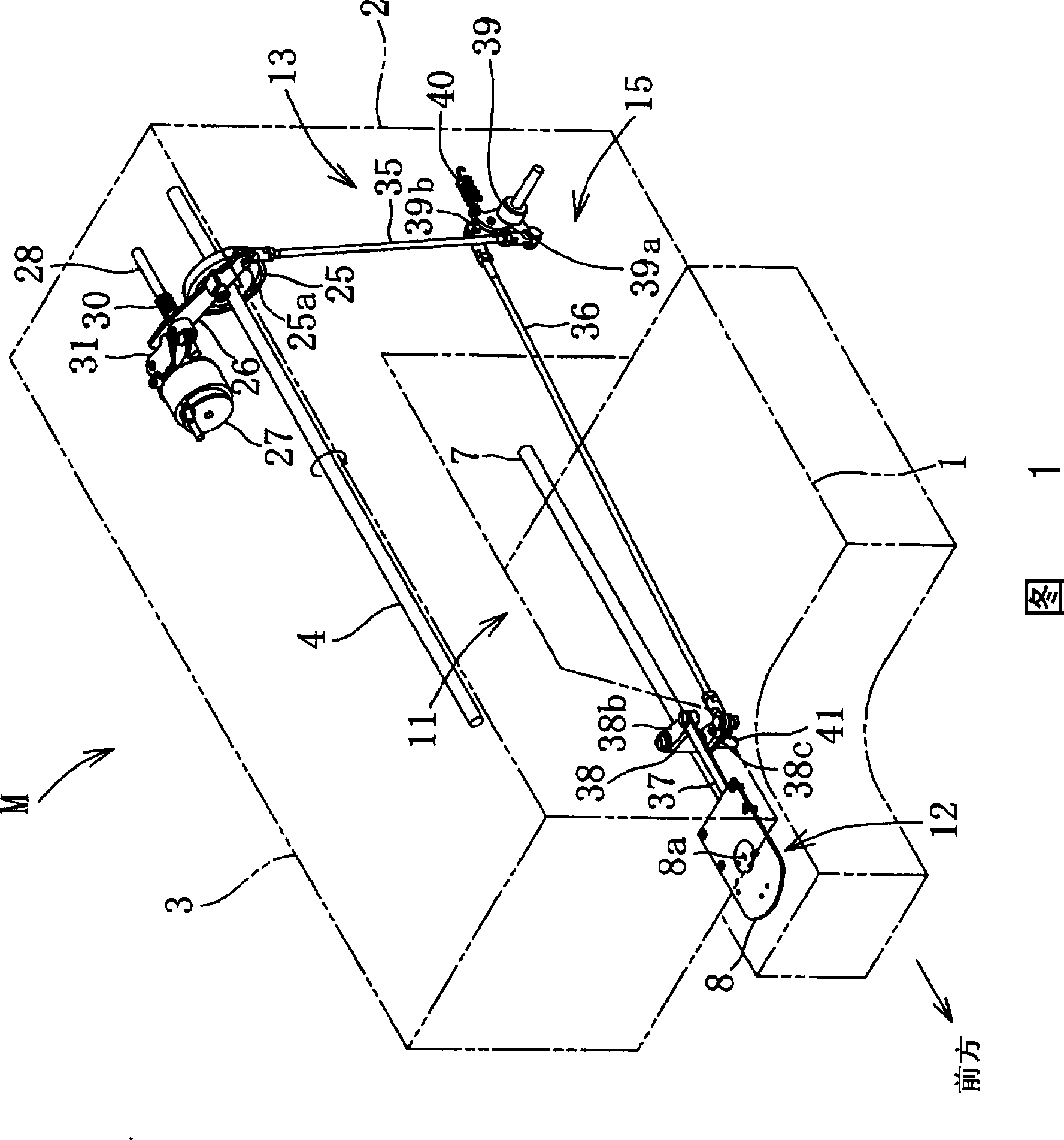
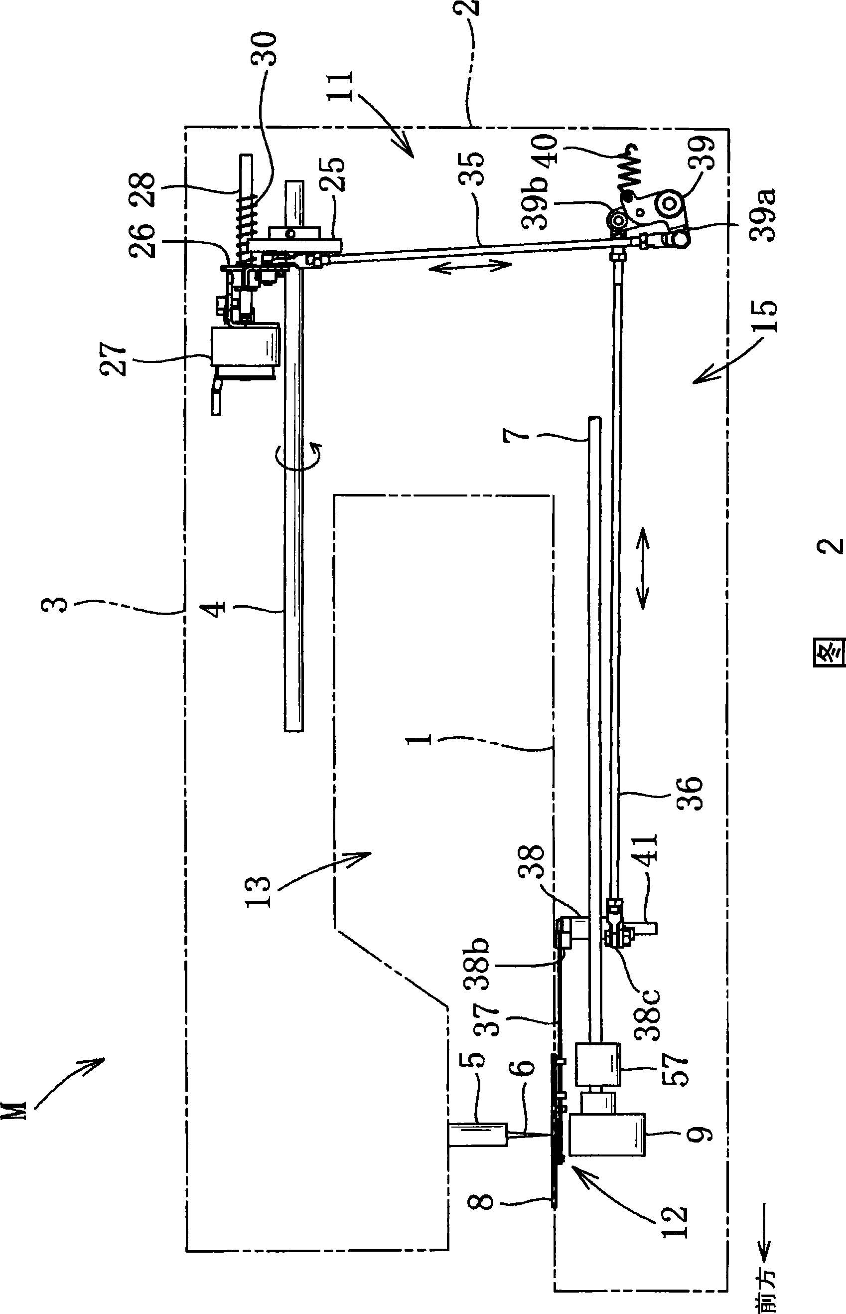
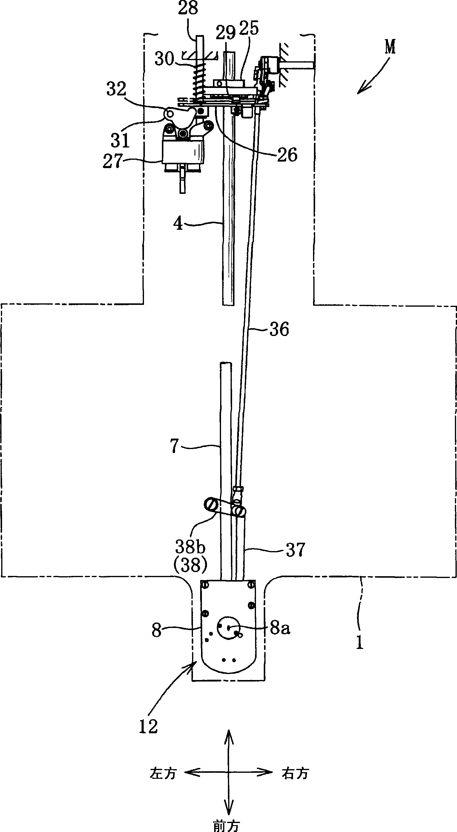
[0049] Figure 1~ Figure 4 As shown, the sewing machine M includes a bottom plate 1 , a column 2 and a machine arm 3 . A needle plate 8 is detachably mounted on the front portion of the base plate 1 . Column 2 erects upwards from the rear upper surface of base plate 1 . The arm 3 extends forward from the upper end of the column 2 so as to face the bottom plate 1 .

[0050] The arm 3 has inside it a sewing machine main shaft 4 extending in the front-rear direction. The sewing machine main shaft 4 is rotated by transmission from a not-shown sewing machine motor. The sewing machine main shaft 4 drives a needle bar drive mechanism and a thread take-up drive mechanism provided on the front inner side of the machine arm 3 . The needle bar driving mechanism drives the needle bar 5 (see FIG. 2 ) in the vertical direction. The thread take-up drive mechani...


PUM


Abstract

A thread cutting apparatus for a sewing machine according to the present invention is arranged in which a spindle for supporting a movable knife beneath a needle plate is located closer to the location of an upper thread loop than the location of a needle hole provided in the needle plate. The apical portion of the movable knife faces the loop opening of the upper thread loop frontwardly of the location of the needle hole. The apical portion of the movable knife that oscillates forward and backward around the spindle enters the loop opening of the upper thread loop from a direction perpendicular to the loop opening. Even when the upper thread loop is interrupted in the shape by the development of a hitch stitch, the movable knife can certainly catch the upper thread loop and cut the threads in combination with a stationary knife.

Description

technical field [0001] The present invention relates to a thread cutting device, which includes: a thread cutting mechanism for cutting upper and lower threads by using a fixed knife and a movable knife, and a thread cutting driving mechanism for driving the thread cutting mechanism, which is assembled on a sewing machine with a shuttle. Background technique [0002] There is a sewing machine provided with a thread cutting device including a movable knife and a fixed knife between a needle plate and a shuttle arranged on the lower side of the needle plate. The movable knife is moved by power transmission from the main shaft of the sewing machine at the end of sewing. The moving movable knife catches the upper and lower threads extending from the processed cloth, and then cuts the upper and lower threads between itself and the fixed knife. [0003] For example, a sewing machine disclosed in Japanese Laid-Open Patent Publication No. 4596 of 1958 includes a linearly movable th...

Claims


Application Information

Patent Timeline
IPC IPC(8): D05B65/02
CPCD05B69/22D05B65/02D05B65/00D05B65/06
Inventor 早川範一中野元就福岛将浩宇野伦子水野雅继
Owner BROTHER KOGYO KK
Learn More