Litzendraht loop antenna and associated methods

a loop antenna and loop antenna technology, applied in the field of loop antennas with increased gain, can solve the problems of not being able to reduce the size of the antenna, the antenna is sometimes large, and the application is not practical, so as to reduce the rf skin effect and increase radiation efficiency and gain.

Active Publication Date: 2007-04-17
HARRIS CORP
View PDF16 Cites 73 Cited by
  • Summary
  • Abstract
  • Description
  • Claims
  • Application Information

AI Technical Summary

Benefits of technology

[0007]In view of the foregoing background, it is therefore an object of the present invention to provide an antenna with reduced RF skin effect and increased radiation efficiency and gain.

Problems solved by technology

Unfortunately, antennas have not been reduced in size at a comparative level and often are one of the larger components used in a smaller communications device.
At very low frequencies, for example, used by submarines or other low frequency communication systems, the antennas become very large, which can be unacceptable.
These antennas, however, are sometimes large and impractical for a specific application.
At lower and lower frequencies however, the radiation resistance of the loop becomes less than the conductor loss resistance, and low radiation efficiency and gain results.
Metals exhibit finite conductivities at room temperature, and conductor loss resistance is a fundamental limitation to the gain and efficiency of small antennas.
However, none of these approaches focuses on reducing the size of the antenna, by providing increasing efficiency and gain in a smaller area.
Furthermore, antennas with solid metal conductors suffer from RF skin effect which is a tendency for alternating current (AC) to flow mostly near the outer surface of a solid electrical conductor as the frequency increases.
RF skin effect greatly reduces the useful amount of conductor cross section, e.g. in a loading coil wire or loop antenna ring.
RF skin effect is a limitation to the gain and efficiency of small antennas.

Method used


Image

  • Litzendraht loop antenna and associated methods
  • Litzendraht loop antenna and associated methods
  • Litzendraht loop antenna and associated methods

Examples


Embodiment Construction

[0016]The present invention will now be described more fully hereinafter with reference to the accompanying drawings, in which preferred embodiments of the invention are shown. This invention may, however, be embodied in many different forms and should not be construed as limited to the embodiments set forth herein. Rather, these embodiments are provided so that this disclosure will be thorough and complete, and will fully convey the scope of the invention to those skilled in the art. Like numbers refer to like elements throughout, and prime notation is used to indicate similar elements in alternative embodiments.

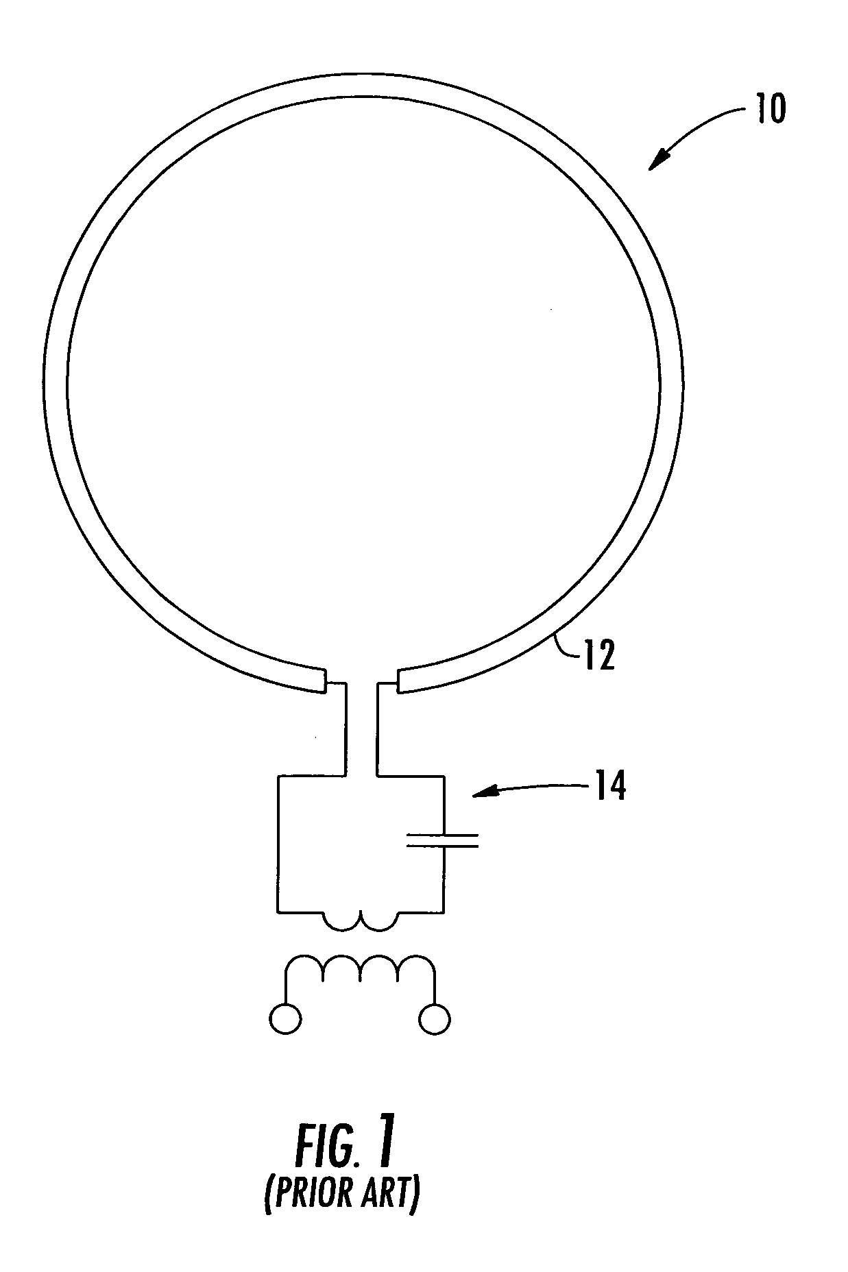
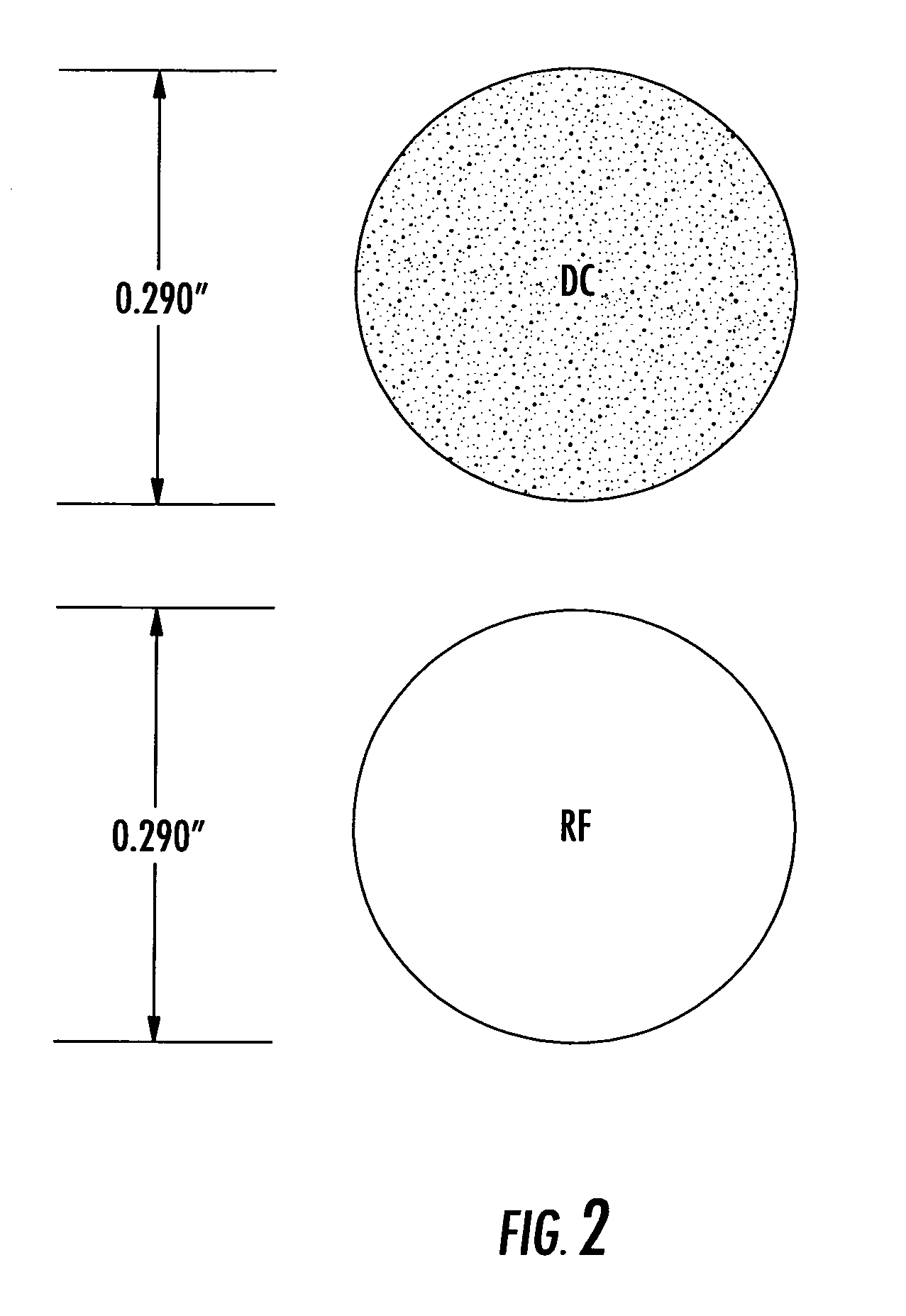
[0017]Referring initially to FIG. 1, a conventional loop antenna 10 will be described. The loop antenna 10 has a solid metal conductor 12 and feed structure 14. As described above, and further illustrated in FIG. 2, solid metal conductors suffer from RF skin effect which is a tendency for current to flow mostly near the outer surface of a solid electrical conductor as the f...


PUM


Abstract

The antenna includes a Litz wire loop having a plurality of individually insulated wires braided together and a plurality of splices therein to define distributed capacitors. A magnetically coupled feed loop is provided within the electrically conductive loop, and a feed structure, such as a coaxial feed line, feeds the magnetically coupled feed loop.

Description

FIELD OF THE INVENTION[0001]The present invention relates to the field of antennas, and more particularly, this invention relates to loop antennas with increased gain and related methods.BACKGROUND OF THE INVENTION[0002]Newer designs and manufacturing techniques have driven electronic components to small dimensions and miniaturized many communication devices and systems. Unfortunately, antennas have not been reduced in size at a comparative level and often are one of the larger components used in a smaller communications device. In those communication applications at below 6 GHz frequencies, the antennas become increasingly larger. At very low frequencies, for example, used by submarines or other low frequency communication systems, the antennas become very large, which can be unacceptable. It becomes increasingly important in these communication applications to reduce not only antenna size, but also to design and manufacture a reduced size antenna having a relatively high gain for ...

Claims


Application Information

Patent Timeline
Patent Type & Authority Patents(United States)
IPC IPC(8): H01Q11/12H01Q21/00
CPCH01Q7/04
Inventor PARSCHE, FRANCIS EUGENE
Owner HARRIS CORP
Why Eureka
Try Eureka