[0011] In another embodiment, the device comprises first and second elongate members. The second elongate member is slideably disposed within a lumen of the first elongate member. The proximal ends of the first and second flexible members are fixed to the second elongate member, and the distal ends of the flexible members are fixed to the first elongate member. The flexible members are operated by sliding the second elongate member distally within the first elongate member, thereby advancing the flexible members through the proximal ports and placing the filter in an expanded state.
[0013] In another embodiment, a plurality of tethers are coupled at a first end to the distal end of the elongate member, and the second end of each of the tethers is coupled to the edge of a parachute filter. In certain embodiments the edge of the filter is mounted about a circular rim. An independently moveable tether is also coupled to the filter edge or the circular rim and is operable at a proximal end. A capture sheath, slideably disposed over the filter and the circular rim, assists in stowing the filter and prevents accidental dislodgment of embolic material during filter closure. The circular rim or filter edge can be rotated into alignment substantially parallel with the elongate member and capture sheath by withdrawing proximally the independently moveable tether. In some embodiments, the circular rim is constructed of a superelastic material, e.g., nitinol. This alignment enables the capture sheath to cover the filter and circular rim to assist with removal of the filter from the vessel.
[0014] In another embodiment, the filter is attached to the elongate member by a plurality of flexible struts. Each of the flexible struts is coupled at a first end to the distal end of the elongate member and coupled at a second end to the filter. The filter is contracted by rotating the elongate member, which in turn winds the flexible struts. A capture sheath is disposed about the elongate member and the filter for
stowage of the filter. As the flexible struts wind, the filter is closed, and the capture sheath is able to cover the flexible struts and filter to assist in removal from the vessel.
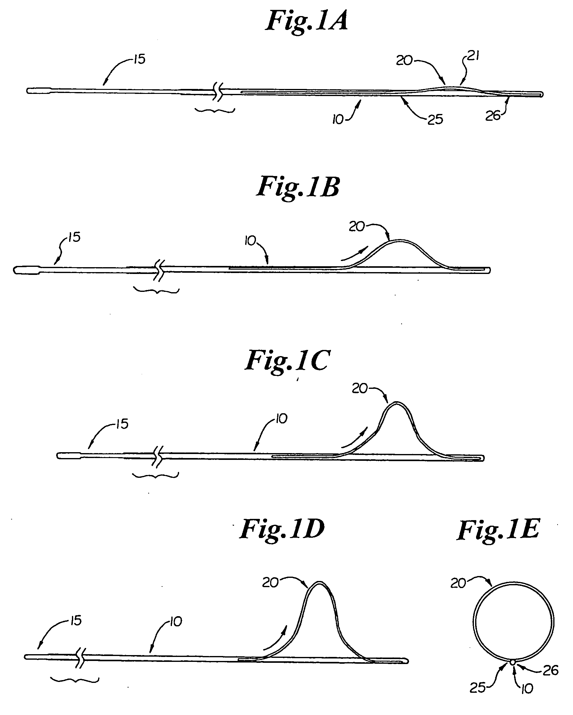
[0016] In a first method of using the filter device having first and second flexible members, the filter is placed in a contracted state. The distal end of the tubular member is inserted percutaneously through an
artery or
vein and advanced into or beyond a
region of interest, typically a
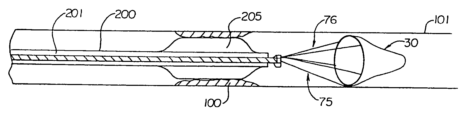
stenotic lesion caused by buildup of atherosclerotic plaque and / or thrombi. The filter is then expanded downstream of the
vascular occlusion by operating the first and second flexible members. In this way, the filter structure conforms to the interior vessel wall with minimum gap, as the elongate tubular member lies against the luminal wall of the vessel. The elongate tubular member then acts as a platform, or guidewire, to guide therapeutic instruments to operate on the
stenosis within the
region of interest. After the
stenotic lesion is removed by endovascular procedure(s), e.g.,
angioplasty,
atherectomy, or
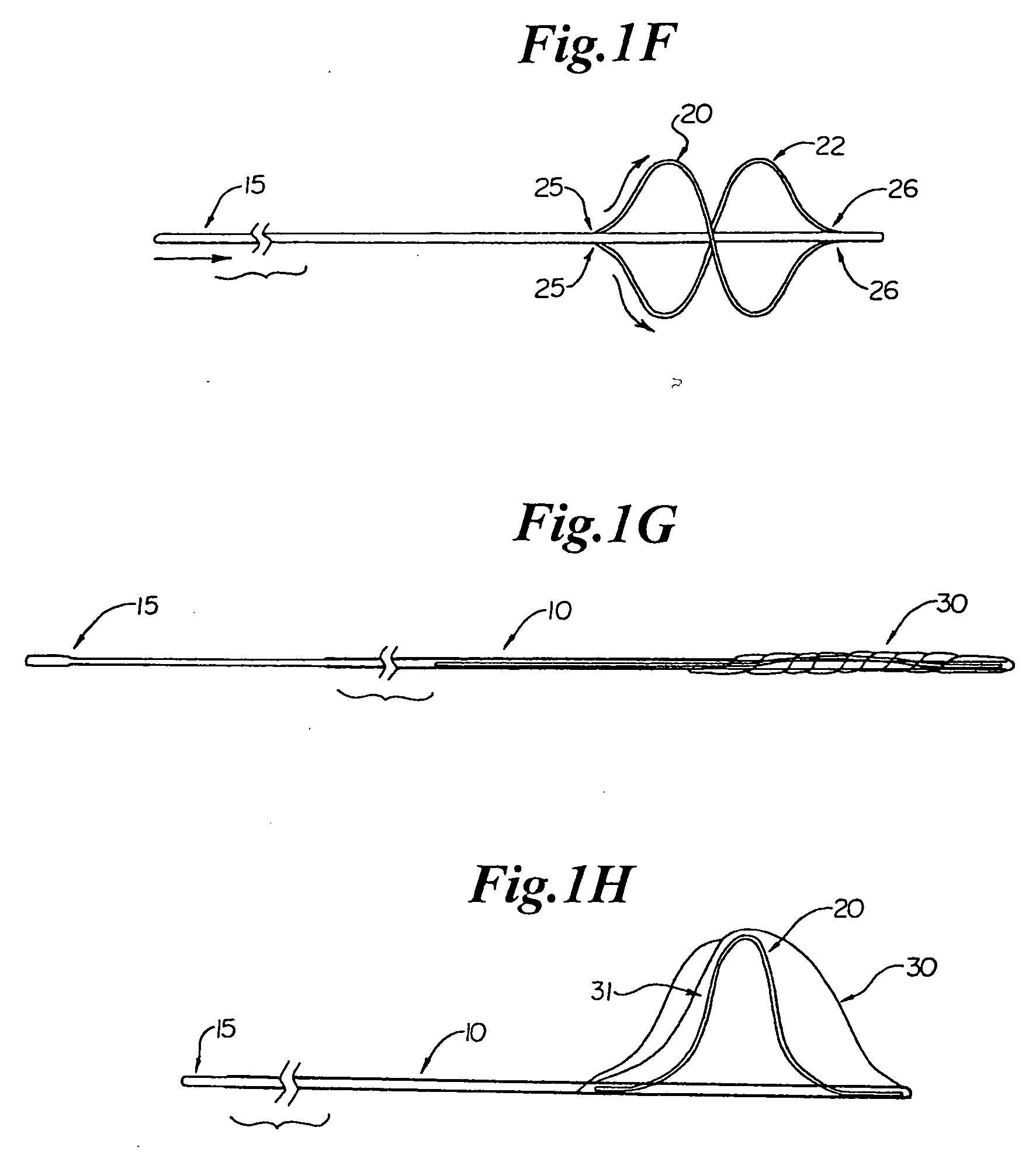
stent deployment, the filter is collapsed and removed from the vessel, together with the captured embolic debris. When the filter is stowed, the flexible members are tightened against the tubular member and constricted by a capture sheath advanced distally over the filter during closure, creating a controlled closure of the filter. In this way, bunching of the filter and undesired release of the captured embolic debris are avoided.
[0019] In another method, using the filter device having a filter coupled to the elongate member by a plurality of flexible struts, the distal end of the elongate member is advanced to a region of interest within a patient's vessel. The capture sheath is withdrawn to release the filter, thereby expanding the filter within the region of interest. After completion of endovascular procedures, the elongate member is rotated, thereby winding the plurality of flexible struts to contract the filter. The capture sheath is advanced distally to cover the wound flexible struts and the filter, thereby providing tight
stowage of the filter and preventing accidental release of captured emboli.
[0020] It will be understood that there are several advantages to using the filter devices and methods disclosed herein for capturing and removing embolic debris during endovascular procedures. For example, the filter devices (1) are particularly well suited for temporary
filtration of blood in any vessel to entrap embolic debris, thereby minimizing neurologic, cognitive, and cardiac complications associated with distal
embolization, (2) conform to the interior vessel wall with minimum gap, (3) can be collapsed to a uniform and predictable size, (4) can be delivered over a guidewire as a rapid exchange device, (5) can be delivered through a lumen of an
angioplasty or
stent deployment device, (6) may include an atraumatic distal tip to minimize vessel wall injury, (7) enable an operator to steer and deploy the filter without kinking, bending, and / or looping of the
catheter because of the small
size ratio of filter to catheter, (8) can pass a large occluding
lesion due to their small
diameter when collapsed, (9) can be used as a guidewire over which a therapeutic catheter may be advanced, and (10) can be used in adult and pediatric patients.

