Anchoring devices for rail fastening clips

An anchoring device and fastener technology are applied in the field of anchoring devices for rail fastening fasteners, and can solve the problems of inaccessibility and hard grinding.

Inactive Publication Date: 2009-03-11
PANDROL LTD
View PDF3 Cites 6 Cited by
  • Summary
  • Abstract
  • Description
  • Claims
  • Application Information

AI Technical Summary

Problems solved by technology

In addition, if image 3 As shown in the circled part F, the local position of this stepped parting line is very critical to the perform

Method used


Image

  • Anchoring devices for rail fastening clips
  • Anchoring devices for rail fastening clips
  • Anchoring devices for rail fastening clips

Examples


Embodiment Construction

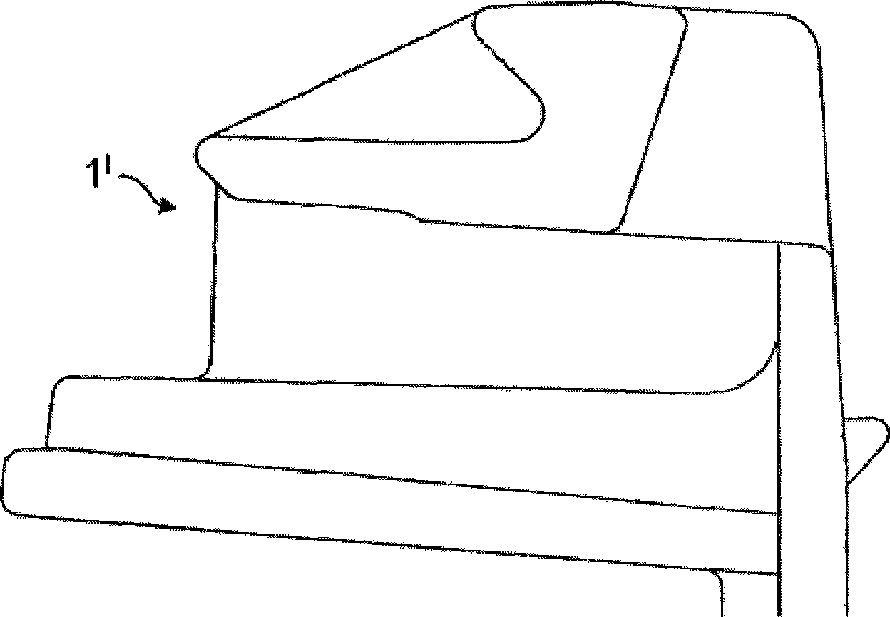
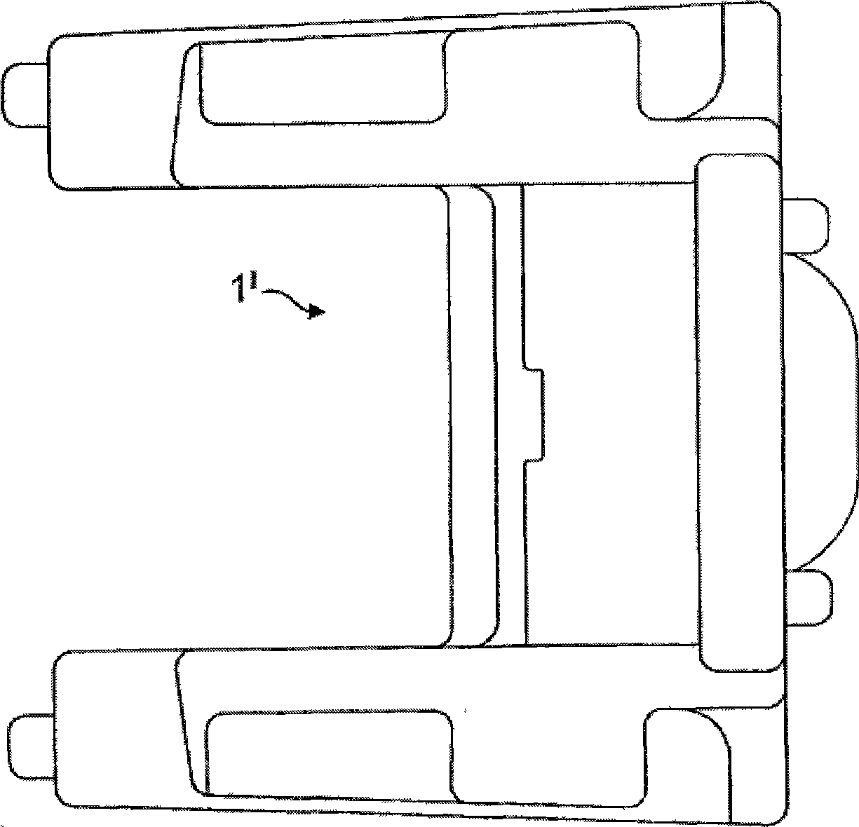
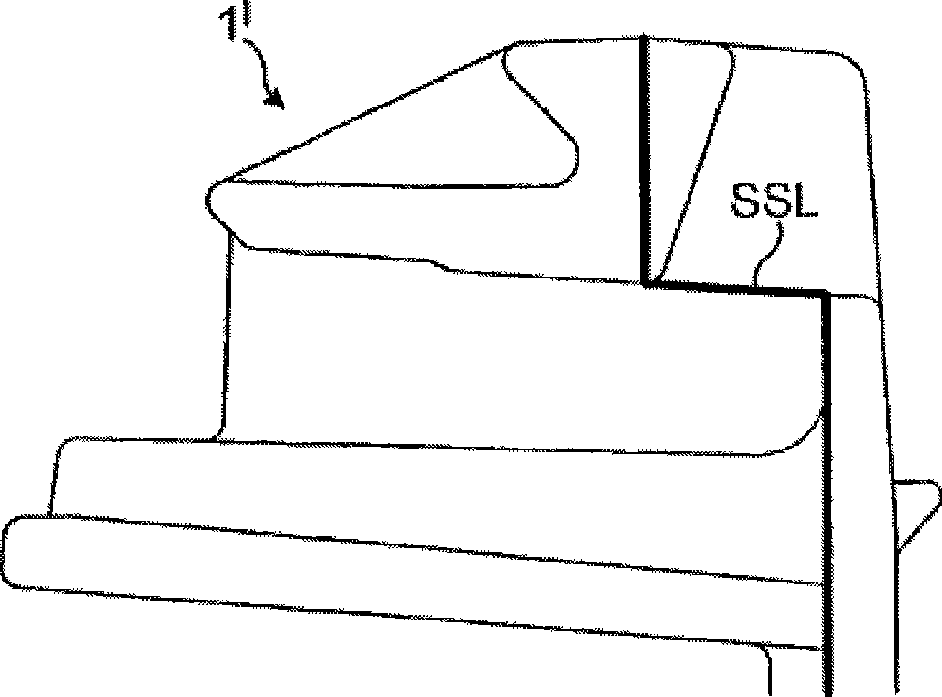
[0030] Figures 5A to 5G An anchoring device (shoulder) embodying the first to third aspects of the invention is shown. Figures 5A to 5G The anchoring device shown comprises a head 1A, a stem portion 1B projecting downwardly from the bottom side of the head 1A, and two mutually spaced apart feet 1C. The stem portion 1B comprises a generally Y-shaped stem 100 connected to the underside of the head 1A at the end of a Y-shaped upper arm 101, and a bend 102. Located at the other end of the Y for preventing the stem from backing out of the concrete into which it is inserted when said stem is in use. Figure 5H shows another embodiment of an anchoring device embodying the first to third aspects of the present invention, wherein one or more nets 1D are provided on the bottom side of said anchoring device 1, the nets 1D will The stem 100 of the anchoring device 1 is connected to the head 1A, and the mesh 1D is used to replace or assist the foot (not shown in FIG. 5H ) when the faste...


PUM


Abstract

The invention discloses a shoulder (1) for retaining a railway rail fastening clip (3), which comprises two interconnected spaced-apart walls (10), between which a portion of the clip (3) to be retained is held in use, and clip-engaging means (11), supported by the walls, for engaging a portion of the clip (3) to be retained, does not have any feature or surface which engages the surface of that clip portion which faces downwardly when the clip is in use. As selected, when the shoulder (1) is located at an effective work direction, the shoulder (1) is used abutting with the rails, at this point, any portion of the contact regions 11OA and 11OB of the shoulder (1) can be seen from upwards to downwards. As selected, when the shoulder (1) is in use, the contact regions 11OA and 11OB of the shoulder (1) both has a same apart horizontal distance from the edge of the foot, wherein, the horizontal distance is measured by a railway rail axis perpendicular to the foot plane.

Description

technical field [0001] The invention relates to an anchoring device for rail fastening fasteners. Background technique [0002] Patent documents WO93 / 12294, WO93 / 12295 and WO93 / 12296 (all applied by the applicant) disclose a rail fastening system. The anchoring device (shoulder) is supported in a "pre-assembled" or "parked" position in which the tip of the fastener is not in contact with the rail. This makes it possible to preload the fasteners on the railroad ties at the factory, with the fasteners being supported in said pre-assembled position, so that when the ties are transported to their intended location, once the rails are placed, they can be The clasp is simply pushed into place. Additionally, when needed to support a rail or jamb insulator (between the rail and the anchor), the fastener can be pushed off the rail, back into the pre-assembled position, or further into a " Insulator shift position" in which the fastener does not rest on the jamb insulator and thus ...

Claims


Application Information

Patent Timeline
IPC IPC(8): E01B9/30
CPCE01B3/28E01B9/686E01B9/303B28B23/0056E01B9/68E01B9/30E01B2205/00E01B9/28
Inventor 斯蒂芬·约翰·考克斯约翰·菲利普·波利尔罗伯特·约翰·汉密尔顿约泽夫·内维达尔马丁·索美赛特保罗·休利特克里斯多佛·加德纳
Owner PANDROL LTD
Why Eureka
Try Eureka