
Electrical switching device

An electrical switch and switchgear technology, which is applied in the field of switching the air-insulated grounding switch and air-insulated grounding switch, can solve problems such as risks, and achieve the effect of prolonging the life and reducing the risk in terms of safety.

Active Publication Date: 2013-10-02
SIEMENS ENERGY GLOBAL GMBH CO & KG
View PDF0 Cites 0 Cited by
  • Summary
  • Abstract
  • Description
  • Claims
  • Application Information

AI Technical Summary

Problems solved by technology

The disadvantage of this is that the resulting arc is still open in the open and thus constitutes a safety risk

Method used


Image

  • Electrical switching device
  • Electrical switching device

Examples


Embodiment Construction

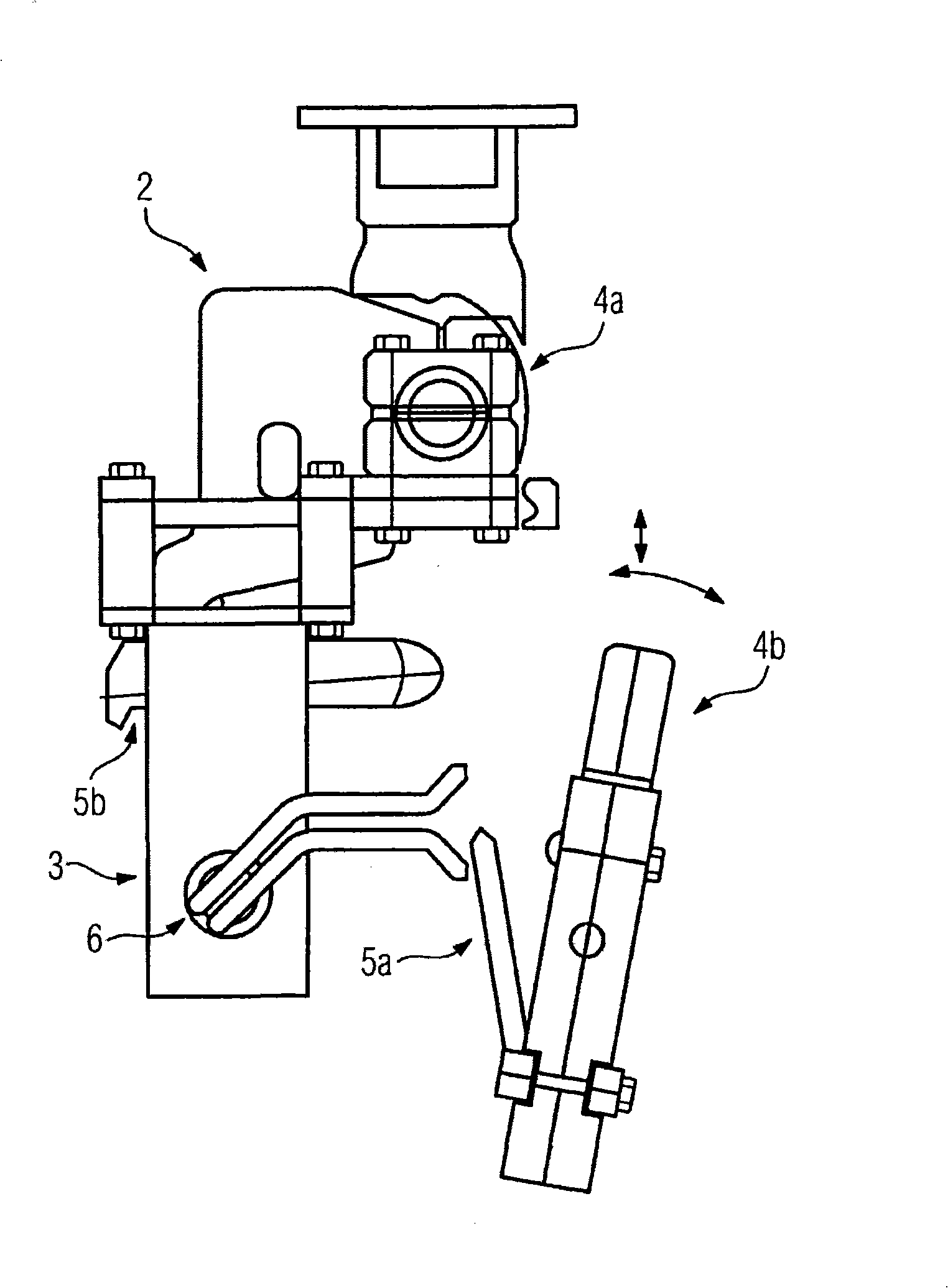
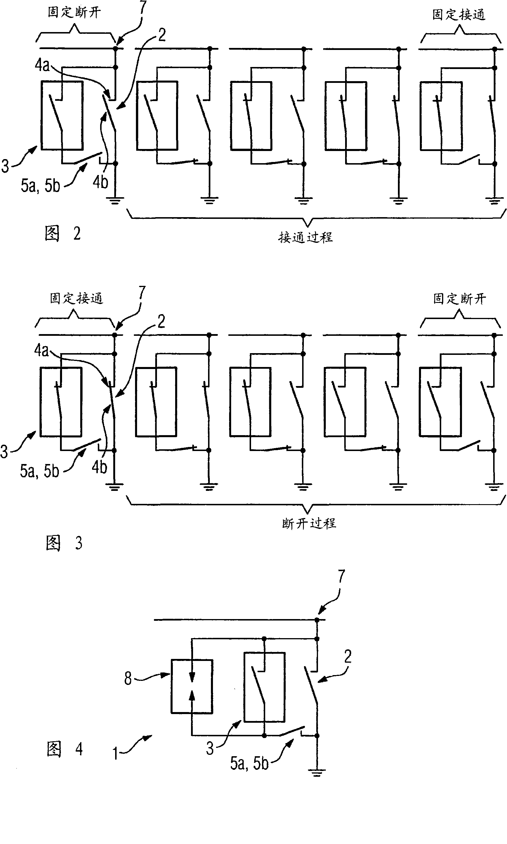
[0022] figure 1 A schematic side view of an air-insulated earthing switch 2 as a first circuit breaker unit is shown as an integral part of an electrical switch (not shown). In the fixed main contact 4 a of the air-insulated earthing switch 2 is integrated a vacuum switch chamber 3 as a second circuit breaker unit. When switching on the main contacts 4a, 4b of the air-insulated earthing switch 2 as a connection of the earthing current path to the voltage potential side, the kinetic energy of the movable main contact 4b of the earthing current path is also switched on at the air-insulated earthing switch 2 The separation points 5a, 5b within the fixed main contact 4a.

[0023] During the rotational movement of the movable main contact 4 b during the switching process, the holder 5 a on the main contact 4 b is locked in the receiving device 6 . And an electrical connection is formed at the separation points 5a, 5b. Through a further rotation of the movable main contact 4b and...


PUM


Abstract

The electrical switching device has an interrupter unit for interrupting and connecting an electrical line. The interrupter unit is connected with other closed interrupter unit. The electrical flashovers produced appear as electric arcs by connecting or interrupting the electrical conductor in the later interrupter unit. The later interrupter unit is switched, when connecting the electrical line before the former interrupter unit. The later interrupter unit is switched, when connecting the electrical line before the former interrupter unit and when interrupting the electrical line, after the former interrupter unit. An INDEPENDENT CLAIM is also included for method for switching an air-insulated grounding switch of electrical line.

Description

technical field [0001] The invention relates to an electrical switching device with a first circuit breaker unit, in particular an air-insulated earthing switch, for disconnecting and connecting electrical conductors. Furthermore, the invention relates to a method for switching the air-insulated grounding switch, wherein no arcing due to voltage breakdown occurs at the air-insulated grounding switch. Background technique [0002] Conventional air-insulated earthing switches are designed as rotating earth wires (Schwenk-Erder) or rotating sliding earth wires (Schwenk-Schub-Erder). When connecting or disconnecting conductors or switching devices to earth potential, the switching process generates capacitive and / or inductive currents which can cause arcing when the main contacts of the earthing switch are at a distance. Since grounding switches are mostly operated in open air installations, this open arc poses a risk to personnel and electrical equipment inside the installatio...

Claims


Application Information

Patent Timeline
Patent Type & Authority Patents(China)
IPC IPC(8): H01H31/00H01H33/12H01H33/66
CPCH01H33/6661H01H33/126H01H31/003
Inventor 托斯滕·扎茨卡斯滕·普罗茨德克·施瑞德
Owner SIEMENS ENERGY GLOBAL GMBH CO & KG
Learn More