Stirring ball mill

一种搅拌式球磨、搅拌轴的技术,应用在谷物处理等方向

Active Publication Date: 2009-03-18
NETZSCH FEINMAHL TECH GMBH
View PDF1 Cites 34 Cited by
  • Summary
  • Abstract
  • Description
  • Claims
  • Application Information

AI Technical Summary

Problems solved by technology

[0003] Since the distance over which the grinding media travels between the vane-shaped elements must be extremely small, it is not possible to prevent the grinding media from penetrating into the grinding outlet during the standstill of the separating device

Method used


Image

  • Stirring ball mill
  • Stirring ball mill
  • Stirring ball mill

Examples


Embodiment Construction

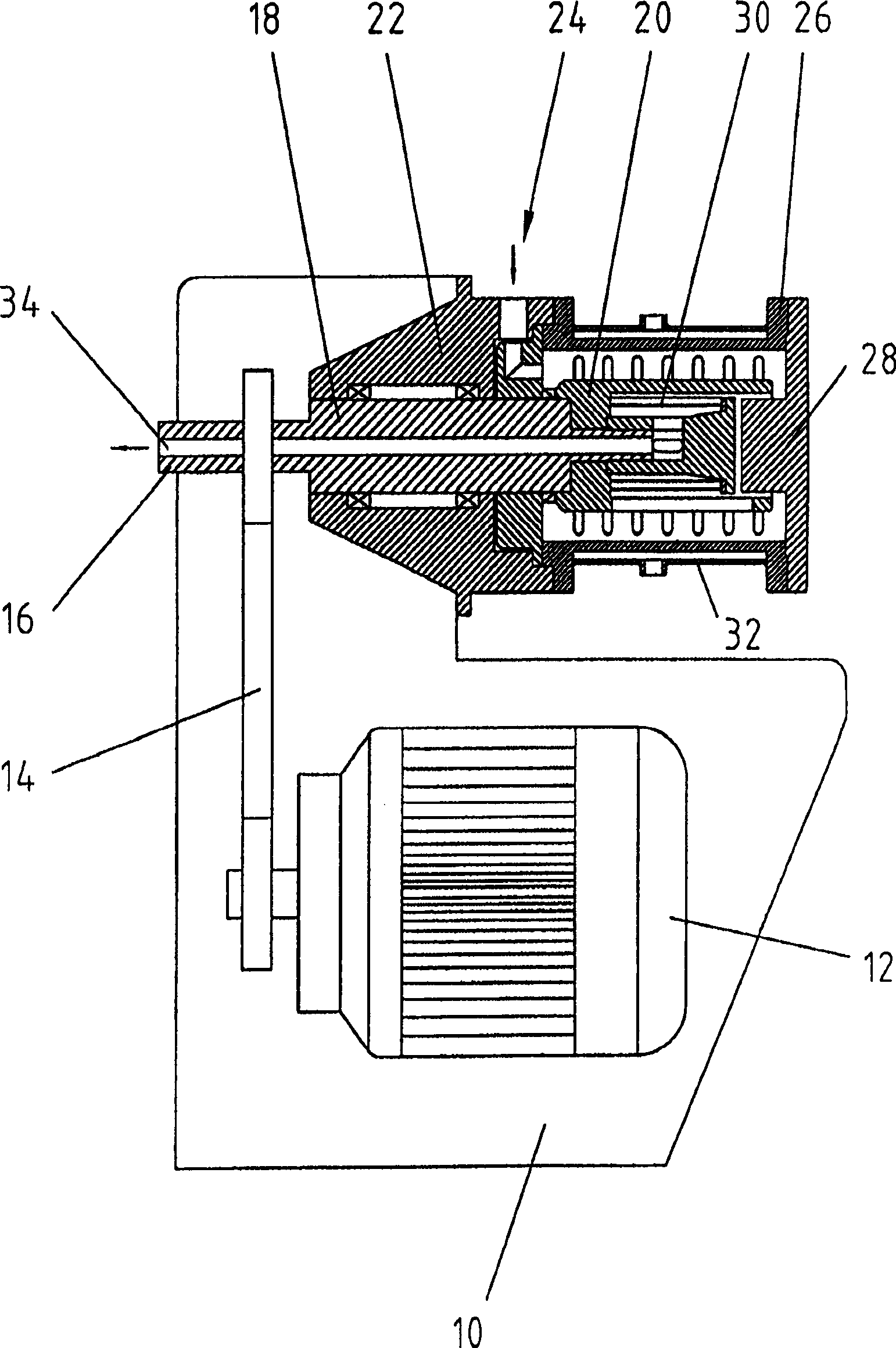
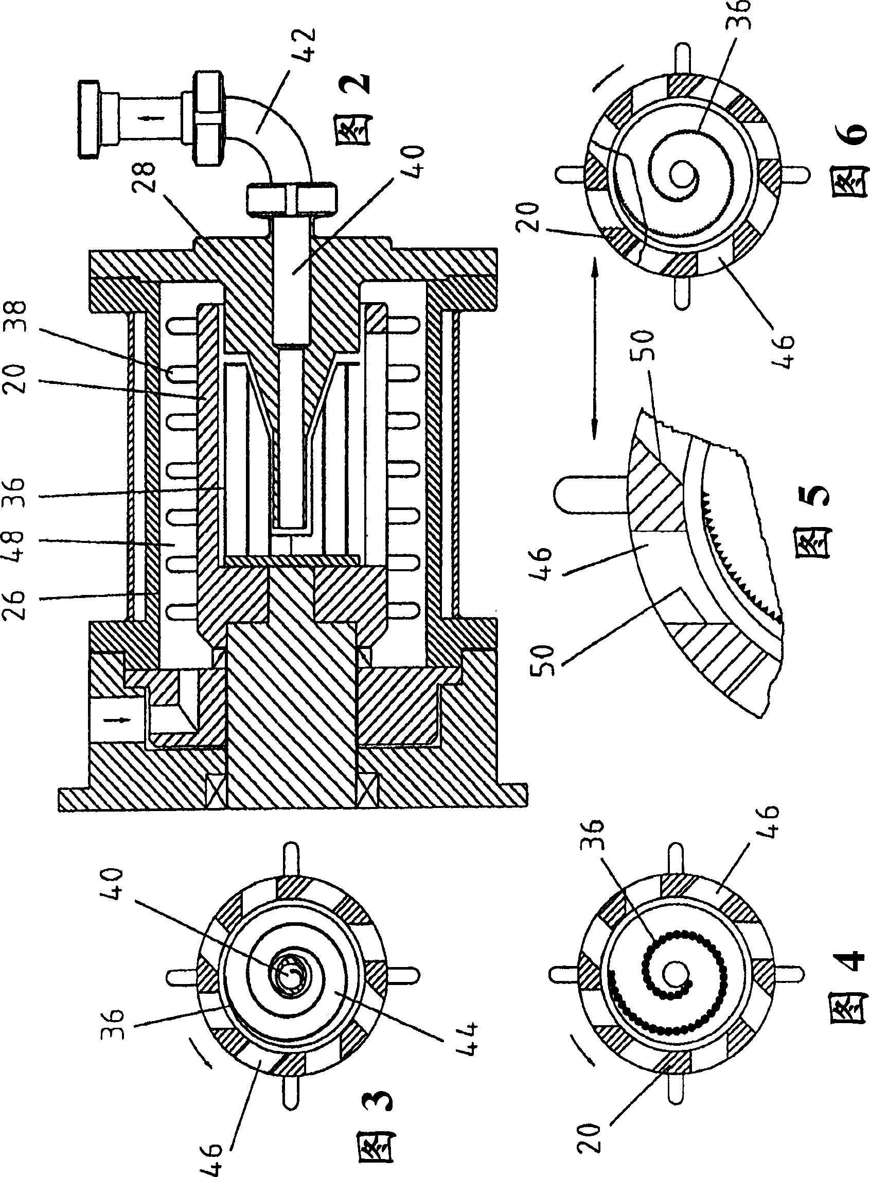
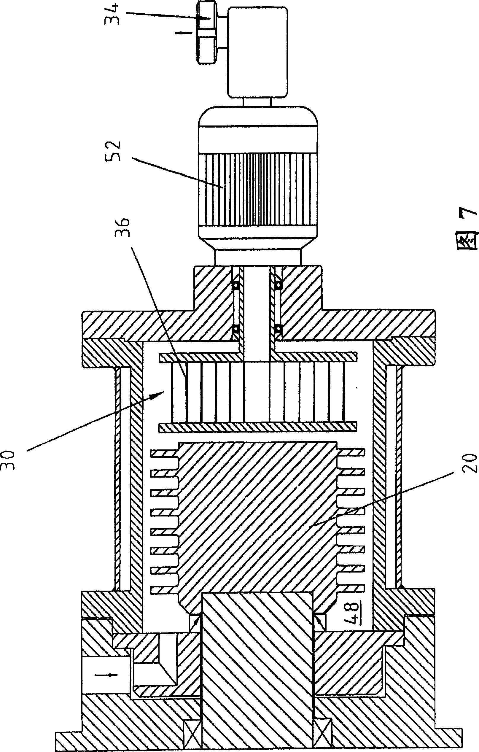
[0081] The agitating ball mill of the present invention consists of a housing 10 in which a driving device 12 in the form of an electric motor is arranged. The drive unit is connected to a drive shaft 16 via a drive belt 14 . The drive shaft transitions into a bearing shaft 18 , which is in turn connected to the stirring shaft 20 . The abrasive material inlet 24 is located on the upper side of the bearing housing 22 . The grinding chamber 48 is surrounded by the grinding container 26, which surrounds the stirring shaft 20 and the bottom surface 28 of the grinding container; In order to cool or heat the grinding container, the grinding container is surrounded by a cooling or heating outer casing 32 , forming a double-layer structure. The ground material leaves the grinding vessel through the central outlet, which starts from the agitator shaft, passes through the bearing shaft until it reaches the drive shaft. Fig. 2 shows the arrangement of spiral 36, and this spiral is pos...


PUM


Abstract

The invention discloses an agitating ball mill, spefically, the invention relates to an agitating ball mill with a cylindrical grinding vessel (26) comprising at least one grinding stock inlet (24) and at least one grinding stock outlet (34), wherein in the grinding vessel (26), an agitating shaft (20) connected with a drive (12) is arranged, which transmits a part of the drive energy to auxiliary grinding bodies (54) which are loosely arranged in the grinding vessel and a separating device (30) arranged in front of the grinding vessel outlet (34).

Description

technical field [0001] The invention relates to an agitating ball mill with a cylindrical grinding container, the grinding container has at least one grinding material inlet and at least one grinding material outlet, a stirring shaft connected to a driving device is installed in the grinding container, and the stirring shaft drives a part The energy is conducted to the grinding media, which are loosely arranged in the grinding container. The ball mill also has a separation device installed in front of the outlet of the ground material. Background technique [0002] Such an agitator ball mill is known from EP 1 468 739 A1. In this horizontally mounted agitator grinder, the grinding vessel is connected to the grinding material inlet and the grinding material outlet. In the grinding vessel itself there is a stirring shaft connected to the drive. The grinding media filled into the grinding chamber is accelerated by the stirring mechanism, so that the grinding materials locate...

Claims


Application Information

Patent Timeline
Patent Type & Authority Applications(China)
IPC IPC(8): B02C17/16B02C23/08
CPCB02C17/161B02C17/00B02C17/16
Inventor H·波什
Owner NETZSCH FEINMAHL TECH GMBH
Why Eureka
Try Eureka