Step motor controlling method

A control device, stepper motor technology, applied in the direction of motor generator control, control system, electrical components, etc., can solve problems such as inability to stop, achieve rapid positioning, prevent excessive rotation speed, and the effect of oscillating motion

Active Publication Date: 2009-03-18
ORIENTAL MOTOR
View PDF0 Cites 7 Cited by
  • Summary
  • Abstract
  • Description
  • Claims
  • Application Information

AI Technical Summary

Problems solved by technology

In addition, since the rotor does not decelerate until it reaches the vicinity of the original position, the rotor may exceed the position where it should stop due to the inertia of the rotor or the load.
In addition, when the above-mentioned inertia is large, the operation will be repeated repeatedly, so that it will not be able to stop.

Method used


Image

  • Step motor controlling method
  • Step motor controlling method
  • Step motor controlling method

Examples


Embodiment Construction

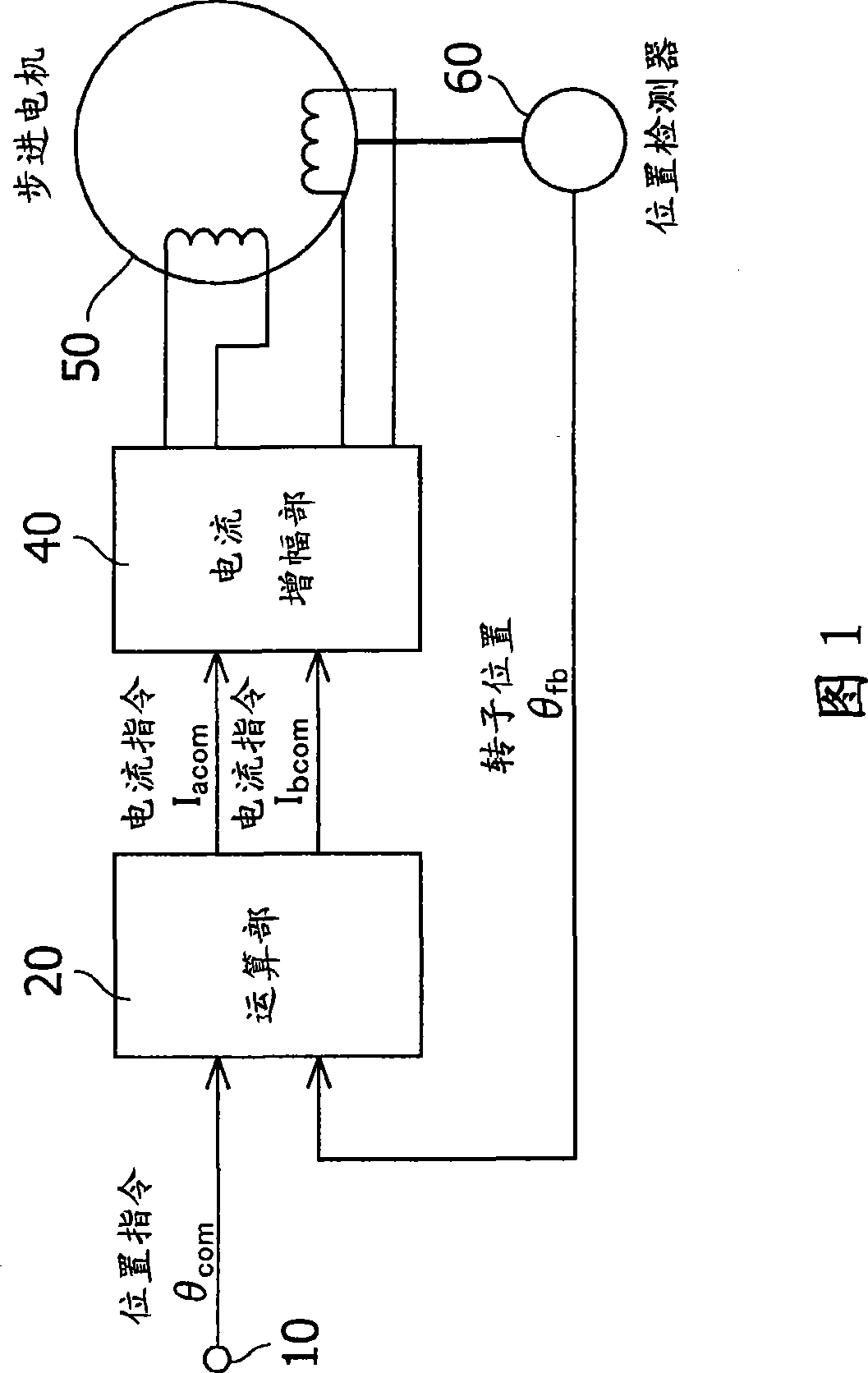
[0053] FIG. 1 is a block diagram showing the overall structure of a stepping motor control device according to an embodiment of the present invention.

[0054] In Fig. 1, through the position command input terminal 10, the position command θ for the rotor of the stepper motor 50 is sent in the form of pulse signal com input to the calculation unit 20 . The position detector 60 is to detect the actual position of the above-mentioned rotor (hereinafter referred to as the rotor position) θ fb If provided, the output thereof is input to the above-mentioned computing unit 20 . In this embodiment, as the stepping motor 50, a stepping motor having a two-phase hybrid structure is used.

[0055] As described below, the calculation unit 20 according to the above-mentioned position command θ com and the actual position θ fb , calculate the phase A current command I acom and B-phase current command I bcom . Current amplifying part 40 is made up of well-known PWM converter, will cor...


PUM


Abstract

The invention provides a control device of a step motor, which is provided with a first judging device (27) which judges whether rotor position deviation is in the prescribed limit, a second judging device (28) which judges whether the positive and negative of the position deviation are corresponding with the positive and negative of velocity deviation and phase setting devices (34-35), winding current instruction phases are set according to position commands when the position deviation is in the prescribed limit, winding current instruction phases are set according to the rotor position, the fixed value and the value which is obtained through adding lead angle correction values of corresponding rotor speed when the position deviation exceeds the prescribed limit and the positive and negative of the position deviation are corresponding with the positive and negative of velocity deviation, and the winding current instruction phases are set when the position deviation exceeds the prescribed limit and the positive and negative of the position deviation are not corresponding with the positive and negative of velocity deviation according to the rotor position, the fixed value, the lead angle correction values of corresponding rotor speed and the value which is obtained through adding the velocity deviation which is multiplied by a regulated factor (Kdo).

Description

technical field [0001] The invention relates to a control device of a stepping motor, in particular to a technology for leading angle control. Background technique [0002] In the control device of the stepping motor, the pulse signal is generally used as the command signal, that is, the position is commanded by the number of pulses, and the speed is commanded by the pulse frequency. In such a control device, for example, Patent Document 1 and Patent Document 2 disclose conventional examples of techniques for setting a lead angle corresponding to the torque of a stepping motor. In Example 1 of the prior art related to Patent Document 1 and Example 2 of the prior art related to Patent Document 2, the current phase of each phase winding is set to θ in the following manner. i . [0003] Example 1 of prior art: [0004] in delta 0 <90°, [0005] θ i = θ com , [0006] in delta 0 >90°, [0007] θ i = θ fb +90°+K V ·ω+K e ·ω·δ 0 , [0008] Among them, θ com ...

Claims


Application Information

Patent Timeline
Patent Type & Authority Applications(China)
IPC IPC(8): H02P8/00H02P8/14
Inventor 宝田明彦
Owner ORIENTAL MOTOR
Why Eureka
Try Eureka