Sealing part

One seal, the other side of the technology, applied in the direction of engine seals, engine components, mechanical equipment, etc.

Active Publication Date: 2010-11-03
ZHONGYE-CHANGTIAN INT ENG CO LTD
View PDF0 Cites 0 Cited by
  • Summary
  • Abstract
  • Description
  • Claims
  • Application Information

AI Technical Summary

Problems solved by technology

However, due to the fatigue nature of the sealing device material itself, it is easy to cause damage, so that the sealing cannot be achieved
In this way, the sealing device needs to be replaced frequently, which affects the working efficiency of the equipment where the flat or arc surface needs to be sealed.
[0004] Moreover, the existing sealing method using sealing rings or sealing gaskets cannot realize dynamic sealing and cannot meet the occasions that require dynamic sealing

Method used


Image

  • Sealing part
  • Sealing part
  • Sealing part

Examples


Embodiment Construction

[0029] The invention provides a sealing element, which is used to ensure the sealing effect of the plane or the arc surface between two components that need to be sealed.

[0030] In order to make the above-mentioned purpose, features and advantages of the present invention more obvious and understandable, the sealing member of the present invention will be further described in detail below in conjunction with the drawings and specific embodiments.

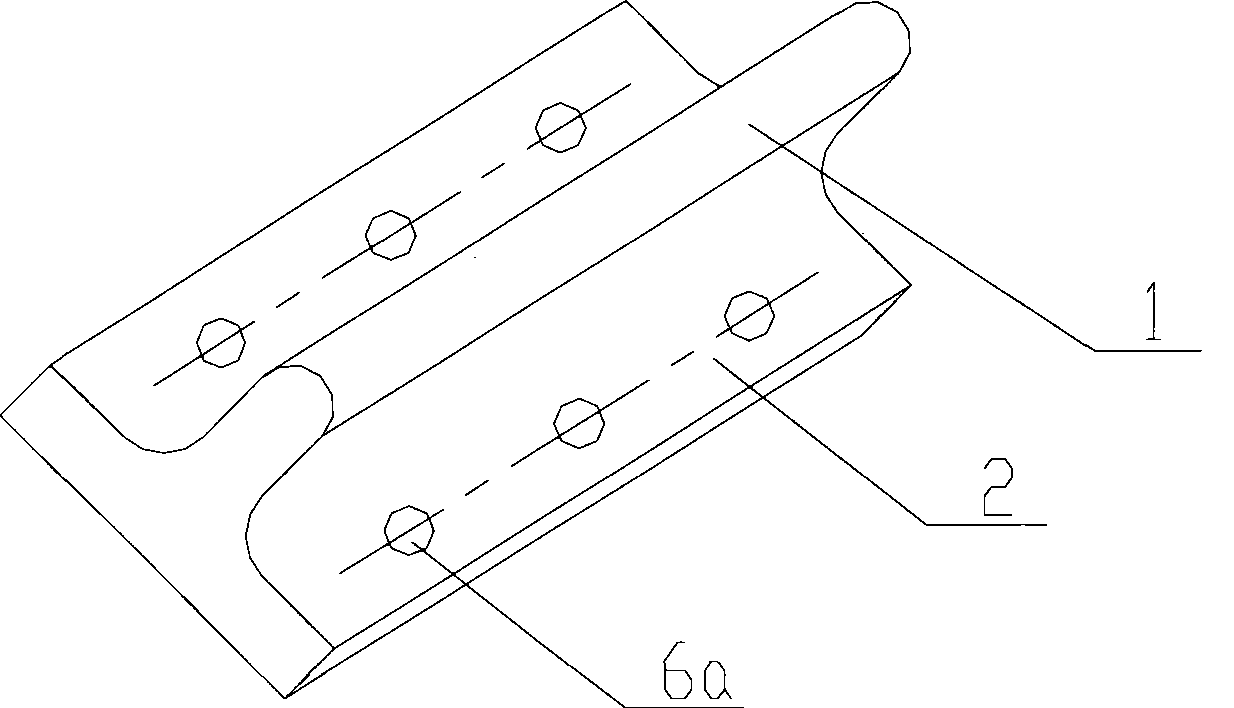
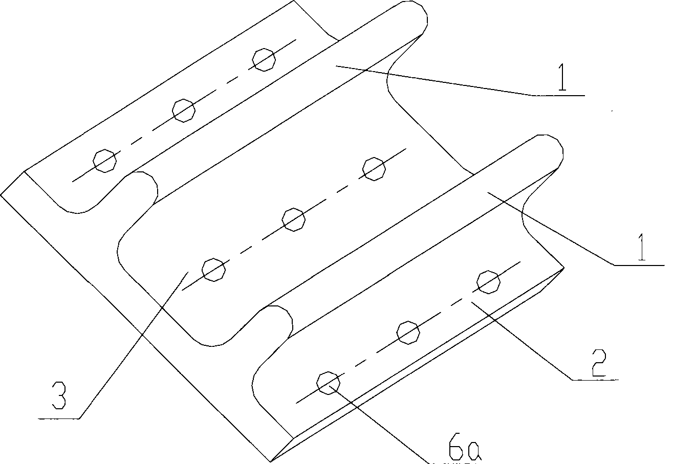
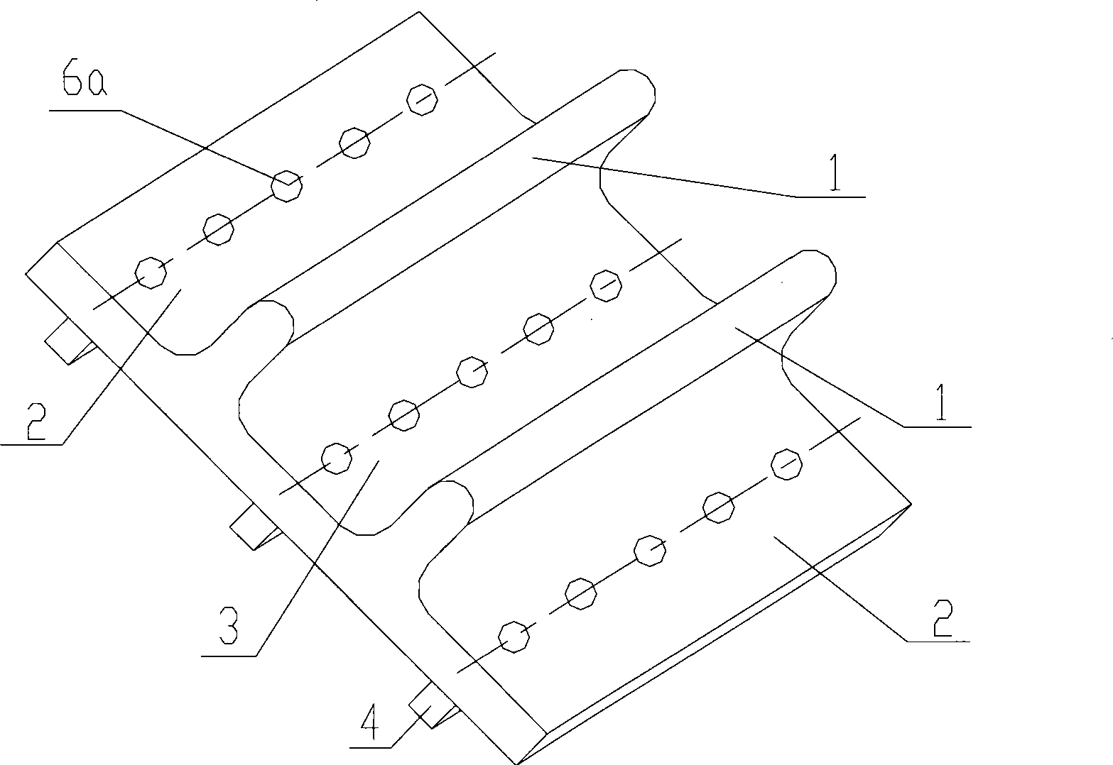
[0031] see figure 1 , which is an isometric view of the first embodiment of the sealing member of the present invention.

[0032] The sealing member described in the embodiment of the present invention can be used for sealing a plane or an arc or a curved surface between two components that need to be sealed.

[0033] The seal in the first embodiment of the present invention includes a protrusion 1 , and the length of the protrusion 1 is equal to the required sealing length of the plane, or equal to the required sealing length o...


PUM


Abstract

The invention provides a sealing member used for sealing two planes or cambered surfaces of a component needing to be sealed. The sealing member at least comprises a protrusion, wherein the length of the protrusion is equal to the length of the planes or the cambered surfaces needing to be sealed. The invention provides the sealing member used for ensuring the sealing effect of the two planes or the cambered surfaces of the member needing to be sealed.

Description

technical field [0001] The invention relates to a sealing device, in particular to a sealing element. Background technique [0002] The sealing between the existing two parts is mostly realized by a sealing ring or a sealing gasket. Since sealing devices such as sealing rings or sealing gaskets are used for sealing, they are generally applied between two coaxial components. And for different shafts, and when the area to be sealed is large, the existing sealing ring or sealing gasket cannot realize sealing well. [0003] Especially when preventing liquid or gas from entering the space between two planes or arc surfaces that need to be sealed, a compressed sealing gasket is usually used to achieve the sealing effect. However, due to the fatigue nature of the sealing device material itself, it is easy to cause damage, so that the sealing cannot be achieved. In this way, the sealing device needs to be replaced frequently, which affects the working efficiency of the equipment...

Claims


Application Information

Patent Timeline
Patent Type & Authority Patents(China)
IPC IPC(8): F16J15/06
CPCF16J15/061
Inventor 高德亮
Owner ZHONGYE-CHANGTIAN INT ENG CO LTD
Why Eureka
Try Eureka