A high temperature and ultra high pressure rotary linear reciprocating dynamic seal test device

A technology of linear reciprocating motion and linear reciprocation, which is used in the extraction of undisturbed core devices, measurements, wellbore/well components, etc. problems, to ensure effective sealing, ensure tightness, and good sealing effect

Active Publication Date: 2022-04-22
SICHUAN UNIV
View PDF0 Cites 0 Cited by
  • Summary
  • Abstract
  • Description
  • Claims
  • Application Information

AI Technical Summary

Problems solved by technology

The physical, mechanical, chemical and biological characteristics of deep rocks are closely related to their in-situ environmental conditions. However, when the existing coring equipment drills deep cores, it will lead to the destruction of the core stress state or stress release, and the strong mechanical disturbance will destroy the core. Authenticity of core stress information and pore pressure information
At the same time, the existing coring equipment cannot maintain pressure and heat preservation, which distorts the gas-liquid phase information and microbial information contained in the in-situ core, and cannot completely scientifically obtain the composition information and occurrence state information of the in-situ core, which greatly increases Uncertainties in Deep Earth Science Research
[0003] During the "in-situ core" rotary drilling and the lifting of fidelity coring equipment after coring, due to the insufficient dynamic sealing performance between the deep in-situ thermal insulation and high-pressure environment simulation cabin and the end structure of the fidelity coring tool, the simulation There is a risk of overflow of high-temperature and high-pressure fluid in the experimental cabin, which will cause fluctuations in environmental parameters such as pressure and temperature in the core storage cabin, making the core unable to maintain its state in the deep in-situ environment

Method used


Image

  • A high temperature and ultra high pressure rotary linear reciprocating dynamic seal test device
  • A high temperature and ultra high pressure rotary linear reciprocating dynamic seal test device

Examples


Embodiment Construction

[0012] The specific embodiments of the present invention are described below so that those skilled in the art can understand the present invention, but it should be clear that the present invention is not limited to the scope of the specific embodiments. For those of ordinary skill in the art, as long as various changes Within the spirit and scope of the present invention defined and determined by the appended claims, these changes are obvious, and all inventions and creations using the concept of the present invention are included in the protection list.

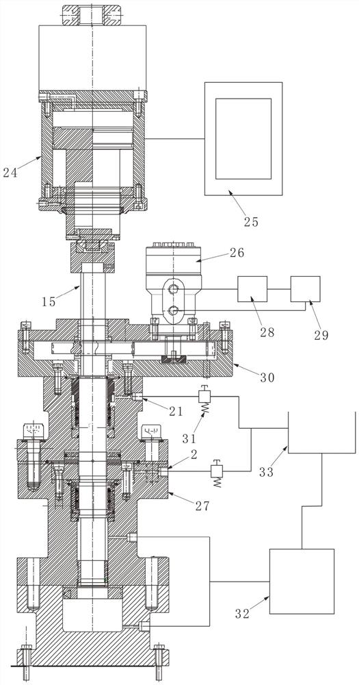
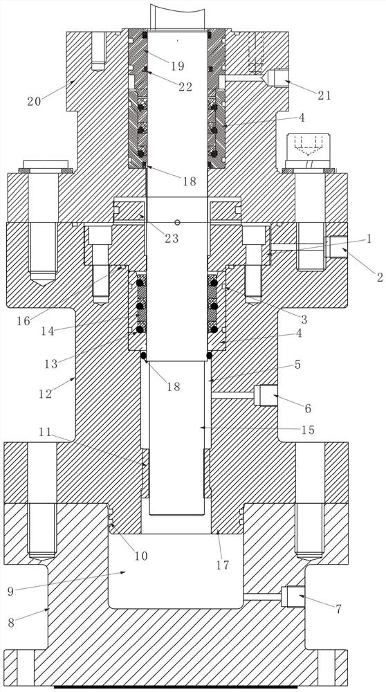
[0013] Such as figure 1 and figure 2 As shown, the high-temperature, ultra-high pressure rotary linear reciprocating dynamic sealing test device of this program includes a rotary linear motion shaft 15, which is connected with a hydraulic motor 26 through a gearbox 30 to realize the rotary motion of the rotary linear motion shaft 15, and the rotary linear motion shaft 15. The upper end of the shaft 15 passes through the g...


PUM


Abstract

The invention discloses a high-temperature, ultra-high-pressure rotary linear reciprocating dynamic sealing test device, which includes a rotary linear motion shaft, which is connected with a hydraulic motor through a gear box to realize the rotary motion of the shaft; the upper end of the rotary linear motion shaft passes through the The gear box is connected with the linear reciprocating motion driving mechanism, and the linear reciprocating motion driving mechanism is connected with the control system to realize the linear reciprocating motion of the shaft; the liquid outlet of the hydraulic motor is connected with the oil cooling system; Both the pressure port and the second decompression port are connected to the cooling pool through the overflow valve, the cooling pool is connected to the temperature rise pressure supply system, and the temperature rise pressure supply system is respectively connected to the first liquid supply port and the second liquid supply port. This solution provides a two-stage decompression dynamic seal (rotary + reciprocating linear) device, which can realize a dynamic seal with a pressure of 140MPa and a temperature of 150°C; at the same time, the device can be used to develop high-temperature and ultra-high-pressure rotary seals with different structures , and verify its sealing ability.

Description

technical field [0001] The invention relates to the field of drilling technology, in particular to a high-temperature, ultra-high-pressure rotary linear reciprocating dynamic sealing test device. Background technique [0002] Requiring energy resources from the deep is the most urgent practical problem in our country at present, it is also a major strategic scientific and technological issue in our country, and it is also a major energy security issue in our country. The in-situ rock mechanical behavior of different depths of rock formations is the leading science and important theoretical basis for deep drilling, deep resource development and utilization, and earth application science. The core and key is how to obtain "in-situ cores" under deep environmental conditions. ", and real-time loading test and analysis were carried out under the in-situ fidelity state. The physical, mechanical, chemical and biological characteristics of deep rocks are closely related to their in...

Claims


Application Information

Patent Timeline
Patent Type & Authority Patents(China)
IPC IPC(8): E21B25/00E21B25/10E21B49/00E21B47/00
CPCE21B25/00E21B25/10E21B49/00E21B47/00
Inventor 谢和平张茹张泽天高明忠陈领李佳南黄伟李怡航杨阳张志龙任利
Owner SICHUAN UNIV
Why Eureka
Try Eureka