Detecting device and detecting method

A detection device and detection card technology, which is applied in the direction of measuring device, measuring device casing, measuring electricity, etc., to reduce the possibility of electrostatic damage, stabilize inspection, and reduce noise

Active Publication Date: 2009-03-25
TOKYO ELECTRON LTD
View PDF1 Cites 6 Cited by
  • Summary
  • Abstract
  • Description
  • Claims
  • Application Information

AI Technical Summary

Problems solved by technology

Furthermore, there is also the disadvantage of having to frequently replace the conductive sheet.

Method used


Image

  • Detecting device and detecting method
  • Detecting device and detecting method
  • Detecting device and detecting method

Examples


no. 1 approach

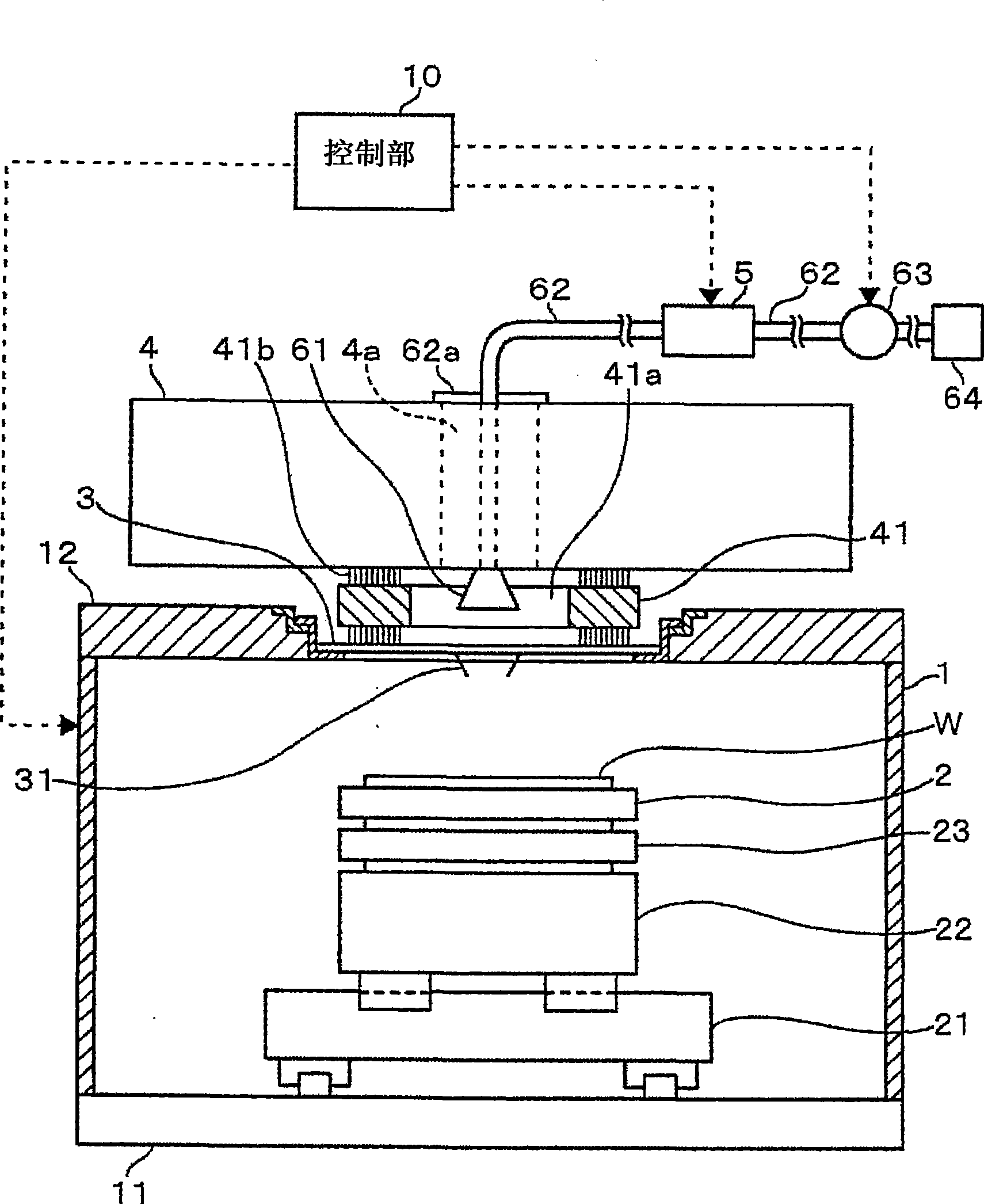
[0053] Such as figure 1 and figure 2 As shown, the detection device according to the embodiment of the present invention includes a housing 1 as an outer casing constituting the main body of the detection device. On the base 11 at the bottom of the frame body 1, there are provided in the following order from the bottom: along the guide rails elongated in the Y direction (the front and back directions of the paper), which are moved along the Y direction by, for example, a ball screw or the like. a driven Y stage 21; and an X stage 22 driven in the X direction by, for example, a ball screw along a guide rail elongated in the X direction. Motors equipped with encoders are respectively provided on the X stage 22 and the Y stage 21, but are omitted here.

[0054]On the X table 22, a Z moving part 23 driven in the Z direction (up and down direction) by an unillustrated motor equipped with an encoder is provided. free to move in the θ direction) as a mounting table wafer chuck 2...

no. 2 approach

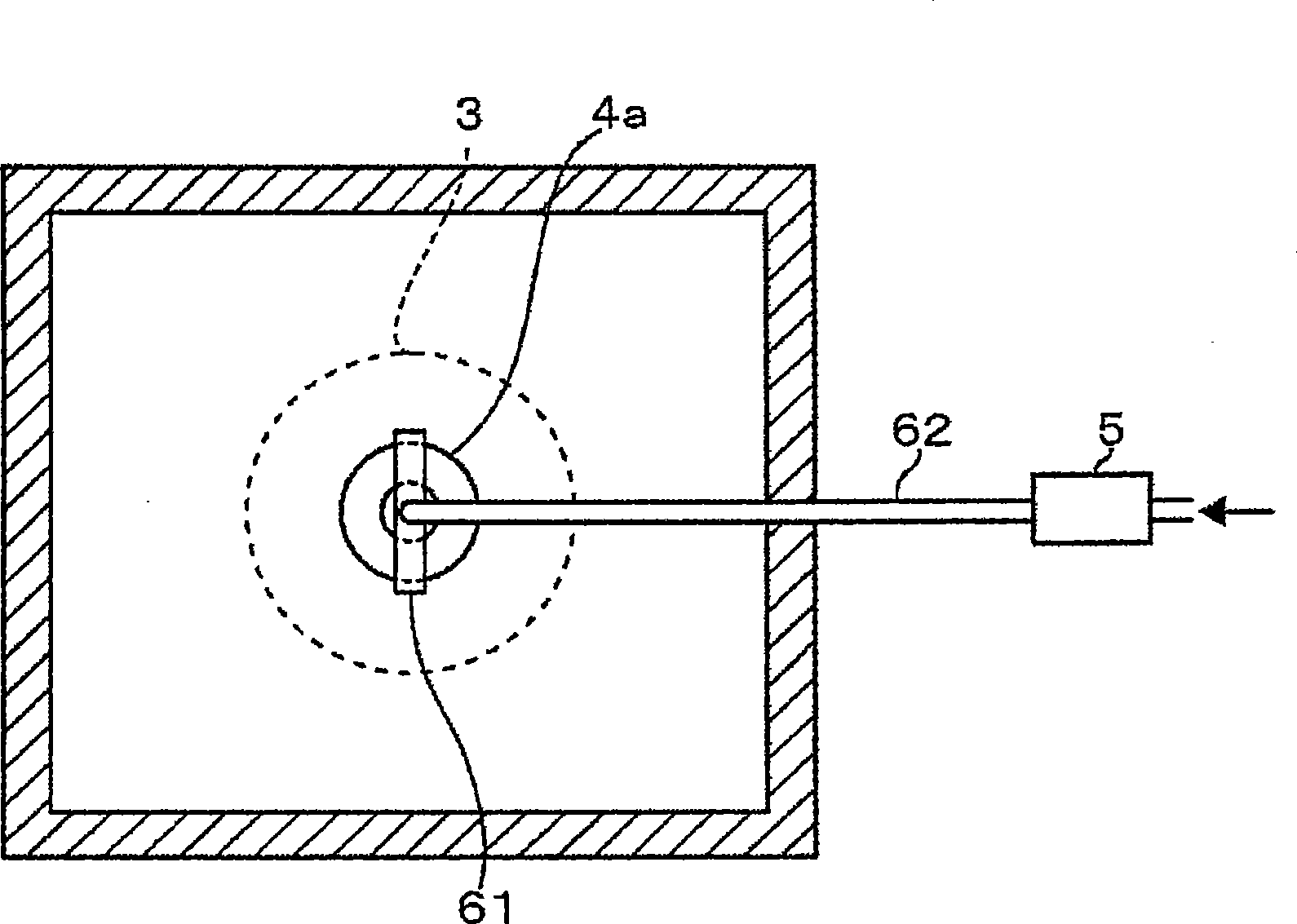
[0070] In this embodiment, if Figure 5 As shown, the nozzle part 61 is provided on the mouth edge part of the opening of the top plate 12 for installing the probe card 3 to eject ionized air toward the probe card 3, and the ionizer 5 is connected from the nozzle part 61 to the ion generator 5. The arrangement of the air supply pipe 62 is carried out in the gap between the test head 4 and the top plate 12 . Such a configuration also has the same effect.

no. 3 approach

[0072] As described above, in the previous embodiment, the imaging unit used for the so-called wafer alignment was not shown, but in this embodiment Figure 6 and Figure 7 The overall configuration is described in , and the camera unit is also described. Such as Figure 7 As shown, the micro camera 7 as the first imaging unit is fixed on the Z moving part 23 below the wafer chuck 2 . In addition, at a height position between the wafer chuck 2 and the tip of the probe 31 , a horizontally long angular cylinder-shaped moving body 8 capable of moving horizontally while facing the wafer chuck 2 is provided. The moving body 8 is guided by a guide rail 81 attached to the lower surface of the top plate 12 and is configured to be horizontally movable by a driving device not shown.

[0073] The moving body 8 is provided with a micro camera 82 as a second imaging unit for taking an image of the wafer W, and the moving body 8 is moved to a predetermined alignment position in advance, ...


PUM


Abstract

The invention provides a detection device and detection method, which can prevent static damage based on detection card electrified IC chip in a detection device using a detection card for detecting electrical characteristics of IC chip on a wafer. Air ionized by using an iron generator is supplied to the detection card from the upper side or the lower side of the detection card. E.g. the iron generator is arranged on the outside of a test head, simultaneously an air supply pipe is arranged around the upper side of the detection card through an opening part in the center of the test head, a nozzle part is arranged on the front end part. Or a camera is carried for shooting an electrode pad of the IC chip on the wafer, the nozzle part is arranged on a moving part capable of moving horizontally between the detection card and a wafer carrier, from which the ionized air is ejected to the detection card.

Description

technical field [0001] The present invention relates to a technique for measuring electrical characteristics of an object to be inspected by bringing a probe into electrical contact with electrode pads of the object to be inspected. Background technique [0002] After forming an IC (Integrated Circuit) chip as a chip to be inspected on a semiconductor wafer (hereinafter referred to as a wafer), a test is performed by probing with a probe device in the state of the wafer in order to investigate the electrical characteristics of the IC chip. In addition, this probing test is performed in order to determine whether or not the circuit parts manufactured so far in the IC chip manufacturing process are appropriate. Such as Figure 11 As shown, this detection device is configured to place a wafer W on a wafer chuck 101 that can move freely in the X, Y, and Z directions and rotate freely around the Z axis, so that the detector of the detection card 102 disposed above the wafer chuck...

Claims


Application Information

Patent Timeline
Patent Type & Authority Applications(China)
IPC IPC(8): G01R31/28G01R31/26
CPCG01R1/04G01R1/067G01R1/07307G01R31/2601G01R31/2886
Inventor 河野功花轮一纪
Owner TOKYO ELECTRON LTD
Why Eureka
Try Eureka