Shift device

A shifting device and shifting fork technology, which is applied in the direction of mechanical control devices, transmission device control, and components with teeth, etc., can solve problems such as longitudinal bending and shifting fork shaft distortion, and achieve simplicity, cost, and space saving , the effect of less structural space

Inactive Publication Date: 2013-01-02
SCHAEFFLER TECH AG & CO KG
View PDF1 Cites 0 Cited by
  • Summary
  • Abstract
  • Description
  • Claims
  • Application Information

AI Technical Summary

Problems solved by technology

However, in the event of an overload, for example due to an unsuitable shifting movement, in particular as in the case according to DE 199 54 545 C1, the distance between the bearing points of the shift fork shaft and the cross-section of the shift fork shaft If the ratio is relatively large, there is a danger of twisting or longitudinal bending of the selector fork shaft

Method used


Image

  • Shift device
  • Shift device
  • Shift device

Examples


Embodiment Construction

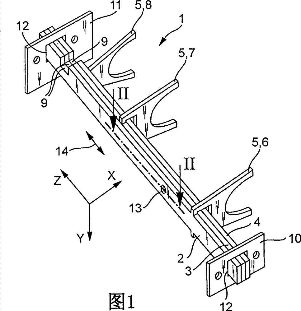
[0021] FIG. 1 illustrates a shift device 1 with a bundle of shift fork shafts 2, 3 and 4. Each shift fork shaft 2, 3, 4 has one of shift forks 6, 7 or 8 and a shift opening 9 as an operating member 5. The shift fork shafts 2, 3, 4 are slid or rolled longitudinally movably in the bearing end caps 10 and 11 along the parallel Z longitudinal direction indicated by the double arrow 14 by means of the support 12 not described in detail.

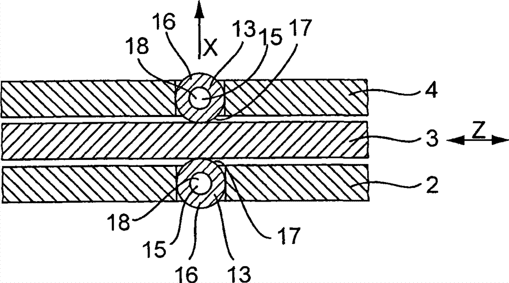
[0022] The shift fork shafts 2 and 4 also each have at least one roller bearing 13. Roller bearing 13 in figure 2 The center is shown in cross-section and each consists of a pin 15 and a roller 16. The pin 15 is fixedly held in the receiving place 17 of the respective shift fork shaft 2 or 4 and the shaft is used for a roller 16 rotatably supported on the pin 15. The roller 16 can be rotatably slid or rolled on the pin 15 around the longitudinal center axis 18. It is also conceivable that instead of one roller, a plurality of rollers are supported...


PUM


Abstract

The invention relates to a shift device (1) having at least two shift rails (2, 3, 4, 19, 20, 21) which are adjacent to one another at least in sections, wherein the shift rails (2, 3 ,4, 19, 20, 21) are mounted at the transmission side so as to be moveable relative to one another and independently of one another in parallel longitudinal directions.

Description

Technical field [0001] The present invention relates to a shift device having at least two shift fork shafts that can be adjacent to each other in sections, wherein the shift fork shafts are movably supported in parallel longitudinal directions opposite to each other and at the same time independently of each other. Transmission side. Background technique [0002] The shift fork shafts are mostly shift components that can move along their main shafts. Operating elements such as shift forks and levers are arranged on them and transmit operating force and torque for shifting, selection, control and interlocking of the mechanism and transmission structural components. And sports. In most cases, these shifting elements are supported on the automobile transmission at least longitudinally at two bearing points. The shift fork shaft on the modern automobile transmission is usually a stamped part of steel plate and has a size correspondingly narrower in one direction of the thickness o...

Claims


Application Information

Patent Timeline
Patent Type & Authority Patents(China)
IPC IPC(8): F16H63/32
CPCF16H63/30F16H2063/3079
Inventor 托马斯・梅利斯克劳斯・克拉默约亨・勒费尔曼
Owner SCHAEFFLER TECH AG & CO KG
Why Eureka
Try Eureka