Hydraulic control method of hydraulic motor rotating speed and device thereof

A hydraulic motor and rotational speed technology, which is applied in the direction of fluid pressure actuators, servo motors, servo motor components, etc., can solve the problems of increased human manipulation, unstable work, and poor ability of the motor to resist load fluctuations, so as to achieve fuel economy. Effect

Inactive Publication Date: 2009-04-01
AVIC LIYUAN HYDRAULIC
View PDF0 Cites 15 Cited by
  • Summary
  • Abstract
  • Description
  • Claims
  • Application Information

AI Technical Summary

Problems solved by technology

The disadvantage is that the motor displacement is determined by the load pressure. When the average load is very low and the fluctuation is large, the motor has poor ability to resist load fluctuations and the work is extremely unstable.
The compound control variable of high pressure and hydraul

Method used


Image

  • Hydraulic control method of hydraulic motor rotating speed and device thereof
  • Hydraulic control method of hydraulic motor rotating speed and device thereof
  • Hydraulic control method of hydraulic motor rotating speed and device thereof

Examples


Embodiment Construction

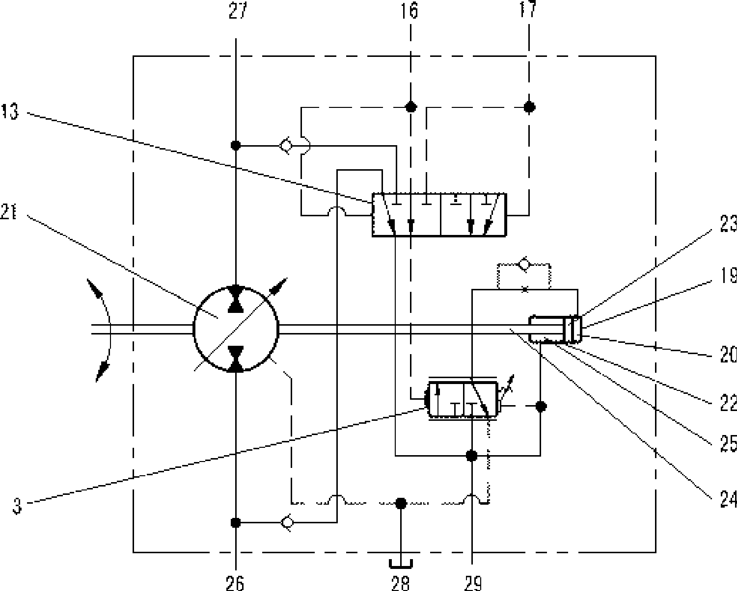
[0024] Example. Hydraulic motor speed hydraulic control method, the hydraulic principle of this method is as follows figure 1 shown. The purpose of adjusting the speed and torque of the hydraulic motor 21 is to achieve the purpose of adjusting the speed and torque of the hydraulic motor 21 by using the external control oil pressure through the speed hydraulic control valve 3 to control the oil circuit of the large chamber 20 and the small chamber 25 in the motor variable cylinder 19; When it is equal to or equal to the set value, the oil circuit of the large cavity 20 of the variable piston cylinder is cut off, and the hydraulic motor 21 is in a state of large displacement and maximum torque; when the speed of the hydraulic motor 21 is higher than the set value and not greater than the rated value, The oil circuit of the large chamber 20 is connected by the speed hydraulic control valve 3, and the displacement and torque of the hydraulic motor 21 gradually decrease; when the ...


PUM


Abstract

The invention discloses a hydraulic motor rotating speed liquid control method and a device thereof. The method utilizes external control oil pressure to control the on/off of the big or small cavity oil circuit of the motor variable case by a rotating speed liquid control valve, thereby achieving the purpose of adjusting the rotating speed and torque of the hydraulic motor. When the rotating speed of the hydraulic motor is not more than the setting value, the oil circuit to the big cavity is cut off and the hydraulic motor is in a state of high flow rate and maximum torque; when the rotating speed of the hydraulic motor is higher than the setting value but not a rated value, the big cavity oil circuit is communicated with the rotating speed liquid control valve and the flow rate and torque of the hydraulic motor are decreased gradually; when the rotating speed of the hydraulic motor exceeds the rated rotating speed, the oil pressure of the hydraulic motor oil inlet is increased and the big cavity oil circuit is cut off by the rotating speed liquid control valve, thereby gradually increasing the flow rate and torque of the hydraulic motor. The method satisfies the self-adaptive ability requirement of the hydraulic driving system of engineering tractors.

Description

technical field [0001] The invention relates to a hydraulic control system, in particular to a hydraulic motor speed control method and device thereof. Background technique [0002] The traction hydraulic system of engineering vehicles (machinery) has requirements for motors. First, the motor and hydraulic system should work in the high-efficiency medium-high pressure range most of the time, so that the working capacity of the components can be fully utilized, and the cost is suitable and sufficient. The second is to make the motor and vehicle self-adaptive to load changes, work at high speed when the load is small to improve work productivity, and work at low speed when the load is large to improve traction, that is, the vehicle drive system automatically adjusts the walking speed according to the change of the external load To adapt to it, the limited power of the engine is adapted to a large range of external load changes, and the power is fully used without overloading. ...

Claims


Application Information

Patent Timeline
IPC IPC(8): F15B11/04F15B13/02
Inventor 曹捷杨宗平罗成舒代雄杨强
Owner AVIC LIYUAN HYDRAULIC
Why Eureka
Try Eureka