Rotary connector

A technology for rotating connectors and rotors, which is applied in the directions of flexible/rotatable wire connectors, connections, electrical components, etc., and can solve the problems of troublesome disassembly and assembly of locking parts and increased cost.

Inactive Publication Date: 2009-04-01
ALPS ALPINE CO LTD
View PDF0 Cites 16 Cited by
  • Summary
  • Abstract
  • Description
  • Claims
  • Application Information

AI Technical Summary

Problems solved by technology

In this case, since the rotor member needs to be able to rotate freely relative to the stator member during the inspection process, if the locking member described in Patent Document 1 is used to maintain the rotational neutral position of the rotary connector before the inspection process, after the inspection process is completed, It is necessary to disassemble the fixed remaining part and reinstall the new locking part, so that the disassembly and assembly of the locking part is very troublesome and the problem of increasing the cost

Method used


Image

  • Rotary connector
  • Rotary connector
  • Rotary connector

Examples


Embodiment Construction

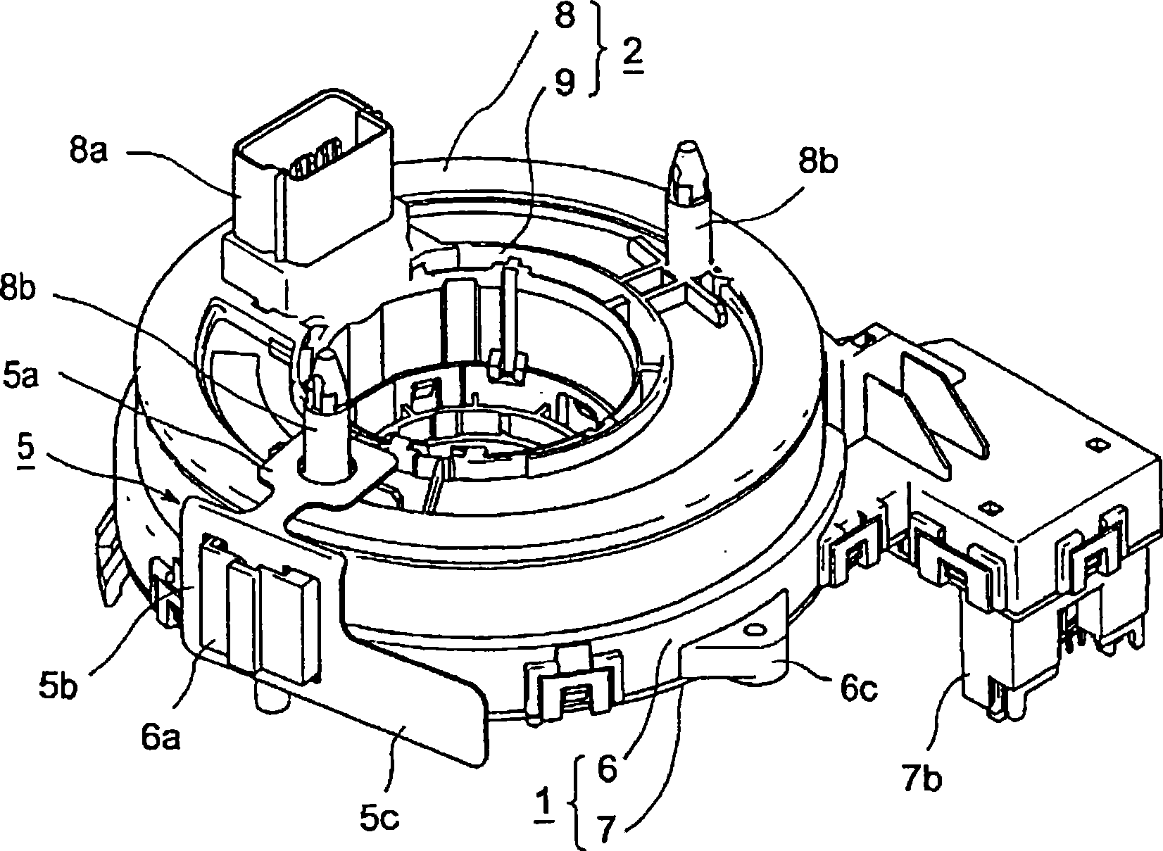
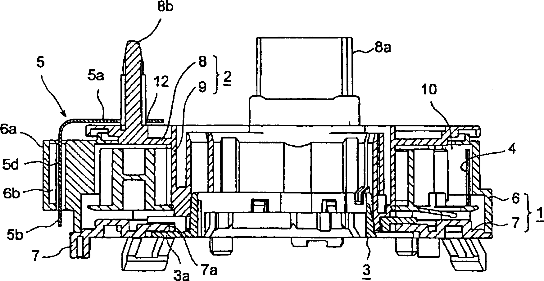
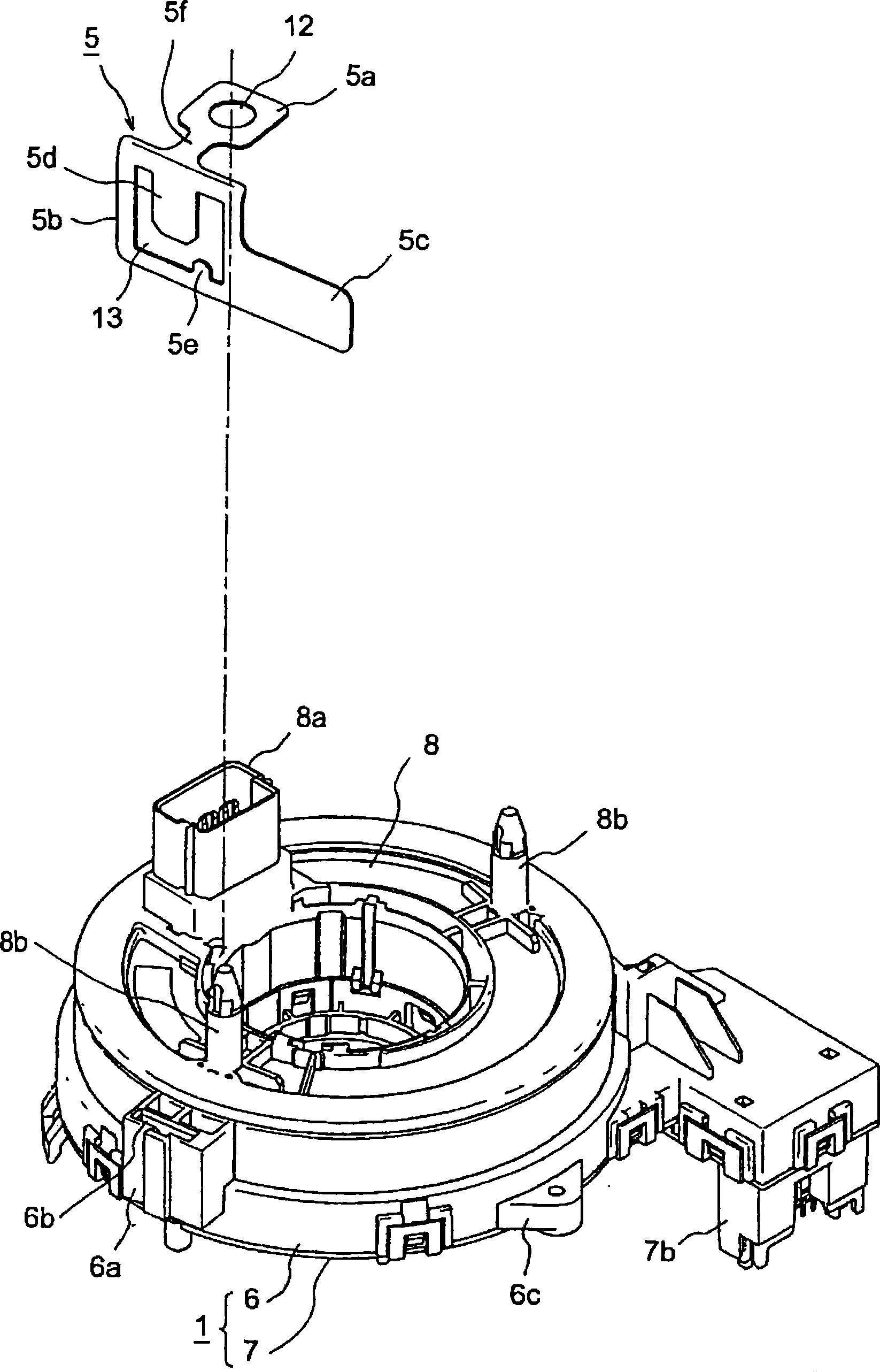
[0019] Hereinafter, specific embodiments of the present invention will be described with reference to the accompanying drawings. figure 1 A perspective view showing a state in which a locking member is attached to a rotary connector according to an embodiment of the present invention, figure 2 yes figure 1 Sectional view of the swivel connector, image 3 expressed in figure 1 A perspective view of the state where the locking part is installed on the rotary connector, Figure 4 yes figure 1 Illustrative drawing of locking components shown.

[0020] As shown in the above-mentioned drawings, the rotary connector involved in this embodiment includes: the stator housing 1 of the stator component, the rotor housing 2 of the rotor component, and the stator housing 1 and the rotor housing 2 are rotatably connected together. The auxiliary rotor 3 and the flexible cable 4 stored and wound in the stator housing 1 and the rotor housing 2, and the locking member 5 can be detached fro...


PUM


Abstract

The present invention provides a rotation connector which can simply hold a rotor component at a rotation neutrality position with a fixing component that is detachably mounted in the period between assembling finishing and executing various examinations to the rotation connector. The fixing component (5) which is formed by PET film, etc. is integratedly formed with a first clamping part and a second clamping part (5a) and (5b). An insertion hole (12) which is formed on the second clamping part (5a) is inserted with a clamping column (8b) which is vertically installed on a top plate part (8) of rotor casing (2). A clamping projection (6a) which is provided on an outer cylinder part (6) of stator casing (1) with a projection mode is formed with a clamping hole (13) that is formed on the second clamping part (5b) through an external embedding mode. Thereby one part of tongues (5d) and (5e) which are formed on the second clamping part (5b) are inserted in the clearance (6b) of clamping projection (6a) from the upper direction and the lower direction. Therefore the free rotation of the rotor casing (2) relatively to the stator casing (1) is prevented and the rotation neutrality positon of rotation connector can be simply held in the period between assembling finishing and executing various examinations.

Description

technical field [0001] The present invention relates to a rotary connector that electrically connects a rotor part and a stator part that are rotatably connected together through a flexible cable, and particularly relates to a rotary connector that is assembled after the rotary connector is assembled and before various inspections are performed. During this period, it is suitable for use as a brake mechanism to temporarily lock the rotor part in the rotational neutral position. Background technique [0002] A flexible cable is generally composed of a pair of housings and a flexible cable, the pair of housings are rotatably connected together, and the flexible cable is stored and wound in an annular space provided between the two housings, and the flexible cable Both ends of the gender cable are respectively drawn out to the outside while being fixed to the two housings. One of the two housings is a stator part and the other is a rotor part. When the rotor part rotates in th...

Claims


Application Information

Patent Timeline
Patent Type & Authority Applications(China)
IPC IPC(8): H01R35/00H01R35/04B60R16/02
Inventor 广桥诚小桥司
Owner ALPS ALPINE CO LTD
Why Eureka
Try Eureka