Method of manufacturing gear from metal sheet and the gear manufactured by the method

A metal plate and gear technology, which is applied in the directions of gears, elements with teeth, belts/chains/gears, etc., can solve the problems of the decrease of the productivity of the disc 100 and the increase of the manufacturing cost of the disc 100, and achieve the effect of eliminating burrs

Inactive Publication Date: 2009-04-08
DENSO CORP
View PDF1 Cites 12 Cited by
  • Summary
  • Abstract
  • Description
  • Claims
  • Application Information

AI Technical Summary

Problems solved by technology

Therefore, the productivity of the disc 100 decreases, and the manufacturing cost of the disc 100 increases

Method used


Image

  • Method of manufacturing gear from metal sheet and the gear manufactured by the method
  • Method of manufacturing gear from metal sheet and the gear manufactured by the method
  • Method of manufacturing gear from metal sheet and the gear manufactured by the method

Examples


Embodiment approach 1

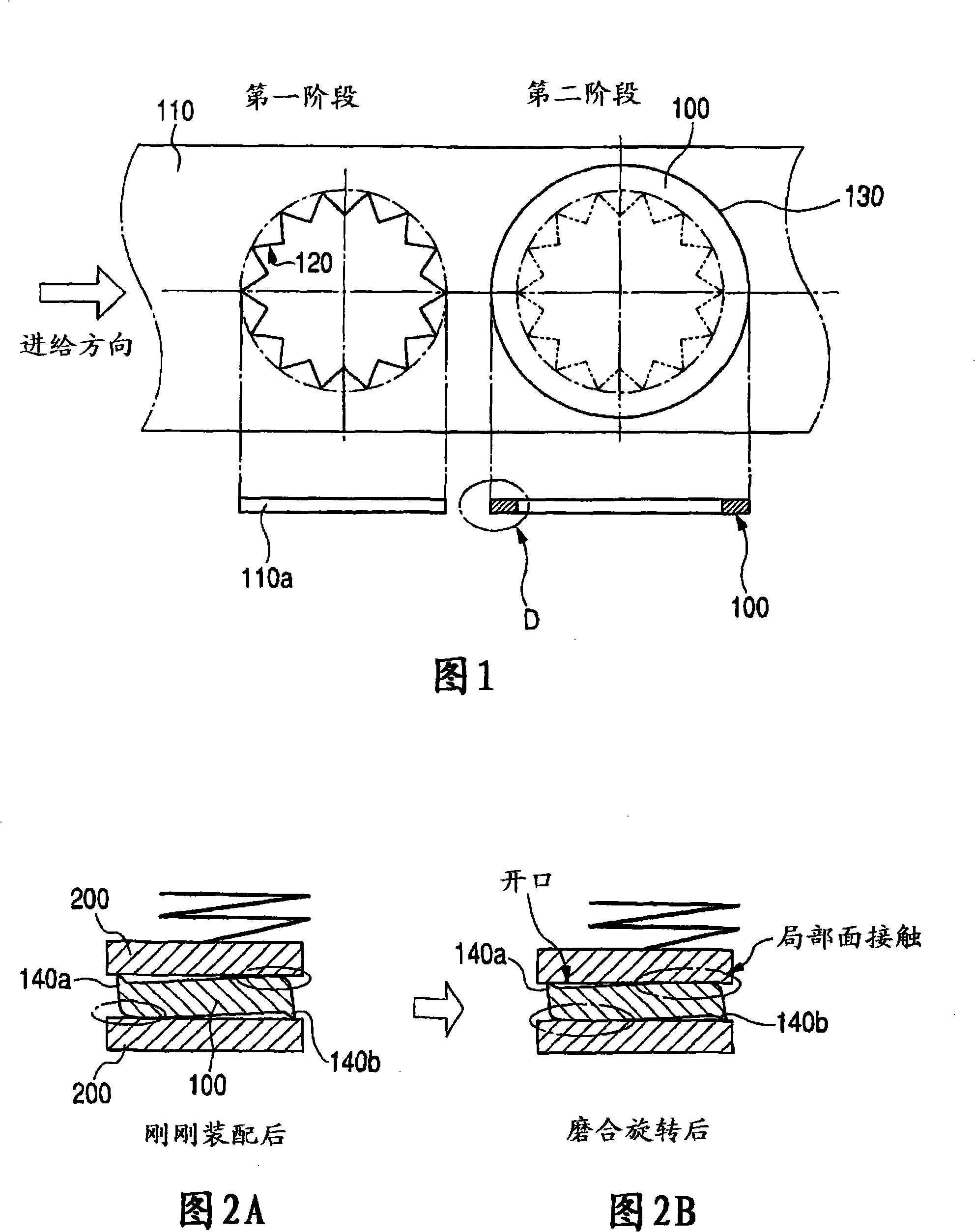
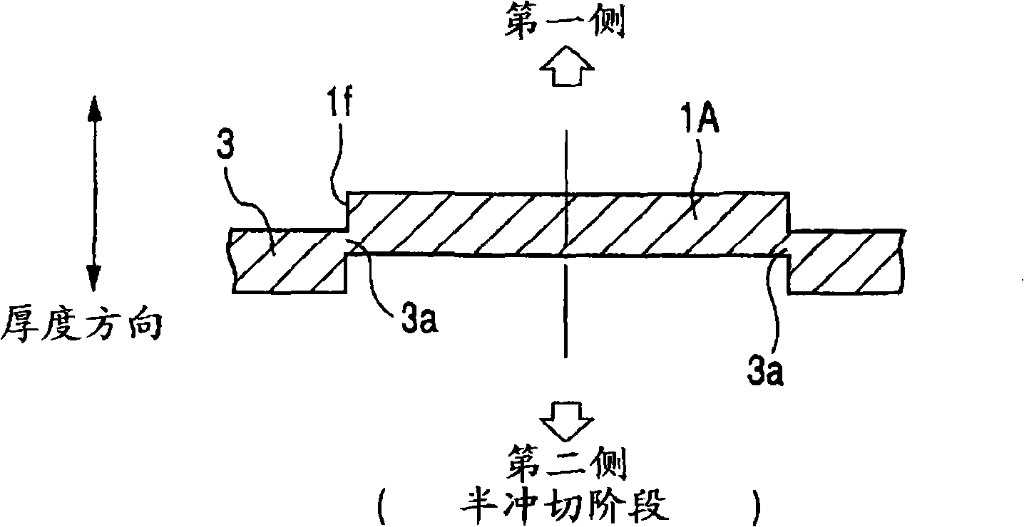
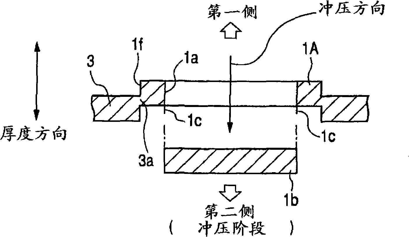
[0048] Figure 3A is a cross-sectional view of a blank produced from a metal sheet in the half blanking stage of the method of manufacturing a rotating disk according to the first embodiment of the present invention. Figure 3B is a cross-sectional view of a blank punched out in the punching phase of the method according to the first embodiment. Figure 3C is a sectional view of a blank obtained as a rotating disc during the separation stage of the method according to the first embodiment. Figure 4A is obtained by Figures 3A to 3C 4B is a longitudinal sectional view taken generally along line A-A of FIG. 4A. Figure 5A is a partial cross-sectional view of a burred rotating disc just placed between two stationary discs, while Figure 5B is after the rotating disc placed between said stationary discs has performed a break-in rotation partial sectional view. The view of the rotating disc in each of Figures 5A and 5B is obtained by zooming in on part B shown in Figure 4B.

[00...

Embodiment approach 2

[0071] In a first embodiment, the stamping phase and the separation phase are performed independently. However, the punching phase and the separating phase can be performed simultaneously.

[0072] Figure 6A is a cross-sectional view of a blank produced from a metal sheet in the half blanking stage of the method according to the second embodiment, and Figure 6B is a sectional view of a blank obtained as a rotating disc during the separation stage of the method according to the second embodiment.

[0073] In this method, a half-cutting stage and a separating stage are performed in sequence to manufacture the rotary disk 1 .

[0074] Such as Figure 6A As shown, in the half blanking stage, half blanking is performed on the first part of the metal plate 3 to produce a blank 1A having an outer peripheral surface and an inner peripheral surface from the first part of the plate 3 and to form a blank 1A on the inner peripheral surface of the blank 1A. tooth profile 1a. A part ...

Embodiment approach 3

[0086] In the second embodiment, since the blank 1A produced in the half blanking stage receives pressing force from only one side of the blank 1A, the side surface of the blank 1A is sometimes warped in the thickness direction of the blank 1A. In the manufacturing method according to the third embodiment, a pressing force application stage is additionally performed to eliminate such warping of the blank 1A.

[0087] Figure 7A is a sectional view of a blank formed in the half blanking stage of the manufacturing method according to the third embodiment. Figure 7B is a partial view in cross-section of the blank and the punch of the press during the compression force application phase of the method. Figure 7C is a cross-sectional view of a blank die-cut as a rotating disk during the separation phase of the process. Figure 7D is an explanatory view showing that warpage is eliminated from the blank at the stage of application of the pressing force.

[0088] In this method, a...


PUM


Abstract

The present invention provides a gear manufacturing method and a gear manufactured by the method. A gear is manufactured in a half blanking stage, a punching stage and a separating stage. In the half blanking stage, half blanking is performed for a columnar portion of a metal sheet. A part of an outer circumferential surface of the blank is disconnected from the other portion of the sheet, while the other part of the outer circumferential surface of the blank is connected with the other portion of the sheet. In the punching stage, an inner portion of the blank is punched in a punching direction to form teeth on an inner circumferential surface of the blank. In the separating stage, the blank is separated from the other portion of the sheet as a gear toward a separation direction opposite to the punching direction by disconnecting the other part of the outer circumferential surface of the blank from the other portion of the sheet.

Description

technical field [0001] The present invention relates generally to a method of manufacturing a gear from a metal plate, and more particularly to a method of manufacturing a gear through the stages of: creating a blank from a metal plate, forming teeth on the inner or outer peripheral surface of the blank Profiles and blanks cut from sheet metal for gears. The invention also relates to gears produced by this method. Background technique [0002] In order to start a driving operation of an engine installed in a vehicle, a starter is used to transmit rotational force generated in a motor to the engine while reducing the rotational speed of the force. For example, a reduced rotation speed type starter is disclosed in published Japanese Patent First Publication No. 2005-113816. The starter has a multi-disc shock absorber to prevent excessive torque transfer in the engine. The shock absorbing device has an internal gear meshing with a plurality of planetary gears to reduce a rot...

Claims


Application Information

Patent Timeline
Patent Type & Authority Applications(China)
IPC IPC(8): B21D53/28B21D28/16B21D28/10F16H55/17
CPCB23P15/14B21D53/28B21D28/16B21K23/00Y10T29/49464Y10T74/19972
Inventor 高田雅广泷桐茂也大野哲生
Owner DENSO CORP
Why Eureka
Try Eureka