High-performance adjusting valve for floating valve seat

A floating valve seat, high-performance technology, applied in the direction of sliding valves, valve details, parts in contact between valve elements and valve seats, etc., can solve the problems of poor use of regulating valves, dusty regulating valves, etc.

Inactive Publication Date: 2017-12-22
林彬
View PDF0 Cites 10 Cited by
  • Summary
  • Abstract
  • Description
  • Claims
  • Application Information

AI Technical Summary

Problems solved by technology

[0005] In order to overcome the disadvantage that the existing regulating valve can only control the flow of liquid, the regulating valve has a lot of dust after long-term use, which leads to the fact that the regulating valve cannot be used well. The technical problem to be solved by the present invention is to provide A floating seat high-performance regulating valve that can control the flow of liquid and prevent dust from the regulating valve, so that the regulating valve can be used better

Method used


Image

  • High-performance adjusting valve for floating valve seat
  • High-performance adjusting valve for floating valve seat
  • High-performance adjusting valve for floating valve seat

Examples


Embodiment 1

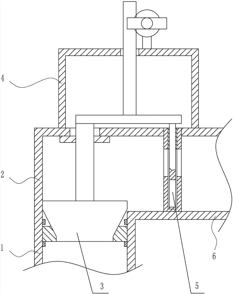
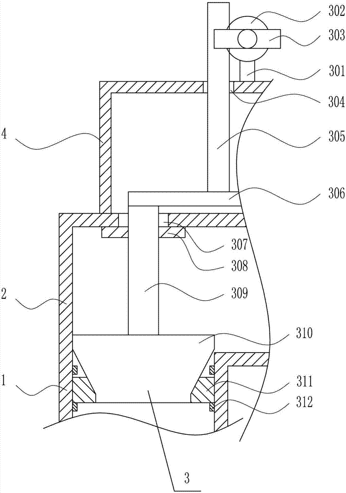
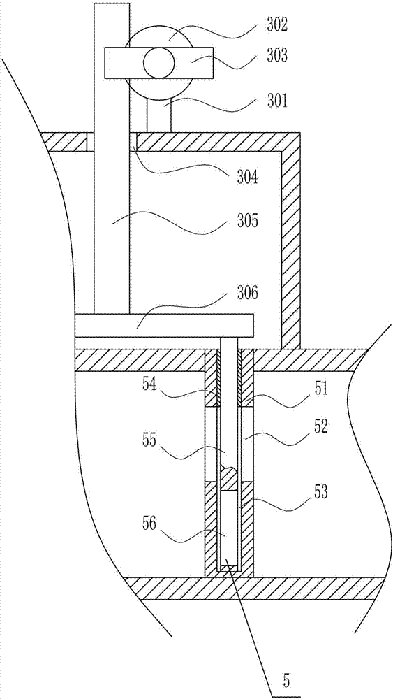
[0037] A floating seat high-performance regulating valve, such as Figure 1-7 As shown, it includes liquid inlet pipe 1, valve body 2, sealing device 3, bracket 4, volume control device 5 and liquid outlet pipe 6, the right side of valve body 2 is connected with liquid outlet pipe 6, and the lower part of valve body 2 is connected with inlet Liquid pipe 1, a bracket 4 is installed between the outer top of the valve body 2 and the outer top of the liquid outlet pipe 6, a sealing device 3 is installed between the inside of the bracket 4 and the liquid inlet pipe 1, and a volume control device 5 is installed in the outlet pipe 6 , the volume control device 5 is connected to the sealing device 3 .

Embodiment 2

[0039] A floating seat high-performance regulating valve, such as Figure 1-7 As shown, it includes liquid inlet pipe 1, valve body 2, sealing device 3, bracket 4, volume control device 5 and liquid outlet pipe 6, the right side of valve body 2 is connected with liquid outlet pipe 6, and the lower part of valve body 2 is connected with inlet Liquid pipe 1, a bracket 4 is installed between the outer top of the valve body 2 and the outer top of the liquid outlet pipe 6, a sealing device 3 is installed between the inside of the bracket 4 and the liquid inlet pipe 1, and a volume control device 5 is installed in the outlet pipe 6 , the volume control device 5 is connected to the sealing device 3 .

[0040] The sealing device 3 includes a vertical rod 301, a gear 302, a rotating handle 303, a rack 305, a horizontal plate 306, a first sealing ring 308, a connecting rod 309, a movable block 310, a second sealing ring 311 and a rubber ring 312, and the liquid inlet Rubber rings 312 a...

Embodiment 3

[0042] A floating seat high-performance regulating valve, such as Figure 1-7 As shown, it includes liquid inlet pipe 1, valve body 2, sealing device 3, bracket 4, volume control device 5 and liquid outlet pipe 6, the right side of valve body 2 is connected with liquid outlet pipe 6, and the lower part of valve body 2 is connected with inlet Liquid pipe 1, a bracket 4 is installed between the outer top of the valve body 2 and the outer top of the liquid outlet pipe 6, a sealing device 3 is installed between the inside of the bracket 4 and the liquid inlet pipe 1, and a volume control device 5 is installed in the outlet pipe 6 , the volume control device 5 is connected to the sealing device 3 .

[0043] The sealing device 3 includes a vertical rod 301, a gear 302, a rotating handle 303, a rack 305, a horizontal plate 306, a first sealing ring 308, a connecting rod 309, a movable block 310, a second sealing ring 311 and a rubber ring 312, and the liquid inlet Rubber rings 312 a...


PUM


Abstract

The invention relates to a floating valve seat regulating valve, in particular to a floating valve seat high performance regulating valve. The technical problem to be solved by the present invention is to provide a high-performance regulating valve with a floating seat that can not only control the flow of liquid, but also protect the regulating valve from dust, so that the regulating valve can be used better. In order to solve the above technical problems, the present invention provides such a floating seat high-performance regulating valve, including a liquid inlet pipe, etc.; the right side of the valve body is connected with a liquid outlet pipe, and the lower part of the valve body is connected with a liquid inlet pipe. A bracket is installed between the outer top of the liquid outlet pipe, a sealing device is installed between the inside of the bracket and the liquid inlet pipe, a volume control device is arranged in the liquid outlet pipe, and the volume control device is connected with the sealing device. The invention achieves the effect of not only being able to control the flow of the liquid, but also preventing the regulating valve from dust, thereby enabling the regulating valve to be used better.

Description

technical field [0001] The invention relates to a floating valve seat regulating valve, in particular to a floating valve seat high performance regulating valve. Background technique [0002] Control valve, also known as control valve, in the field of industrial automation process control, is the final control element that changes the process parameters such as medium flow, pressure, temperature, liquid level, etc. by means of power operation by receiving the control signal output by the adjustment control unit. It is generally composed of actuators and valves. According to the characteristics of the stroke, the regulating valve can be divided into straight stroke and angular stroke; according to the power used by the actuator, it can be divided into three types: pneumatic regulating valve, electric regulating valve and hydraulic regulating valve; according to its function and characteristics There are three types: linear characteristic, equal percentage characteristic and ...

Claims


Application Information

Patent Timeline
Patent Type & Authority Applications(China)
IPC IPC(8): F16K1/00F16K1/42F16K1/46F16K1/52F16K3/02F16K25/00F16K31/54F16K31/12F16K27/12B08B1/00B08B1/02
CPCF16K1/00B08B1/002B08B1/02F16K1/42F16K1/46F16K1/52F16K1/526F16K3/02F16K3/0254F16K25/005F16K27/12F16K31/12F16K31/54
Inventor 林彬
Owner 林彬
Why Eureka
Try Eureka