
Center distance-regulating mechanism for steel plate-forming machine

A technology of adjusting mechanism and forming machine, applied in the direction of metal rolling mill stand, metal rolling stand, metal rolling, etc., can solve the problems of unsatisfactory equipment use effect, high production cost and inconvenience, etc. The effect of low procurement and production maintenance costs, beautiful and compact appearance, and convenient maintenance

Active Publication Date: 2009-05-27
ZHEJIANG JINGGONG SCI & TECH
View PDF0 Cites 10 Cited by
  • Summary
  • Abstract
  • Description
  • Claims
  • Application Information

AI Technical Summary

Problems solved by technology

[0002] The working principle of the adjustment of the distance between the forming wheels of the existing building materials forming equipment basically follows the working method of the current building materials forming equipment, that is, by adjusting the adjustment mechanism installed on the roller axle brackets on both sides of the equipment, the upper or lower roller axles are moved up and down to achieve The adjustment of the distance between the upper and lower wheel axles requires frequent changes in product specifications during the actual production process, and the thickness and shape of the raw material plates are different. Before adjustment, each fastener must be loosened, and after adjustment, each fastener must be tightened. , it is very inconvenient to adjust repeatedly, the production cost of the mechanism is also high, and the use effect of the equipment is not very ideal

Method used


Image

  • Center distance-regulating mechanism for steel plate-forming machine
  • Center distance-regulating mechanism for steel plate-forming machine
  • Center distance-regulating mechanism for steel plate-forming machine

Examples


Embodiment Construction

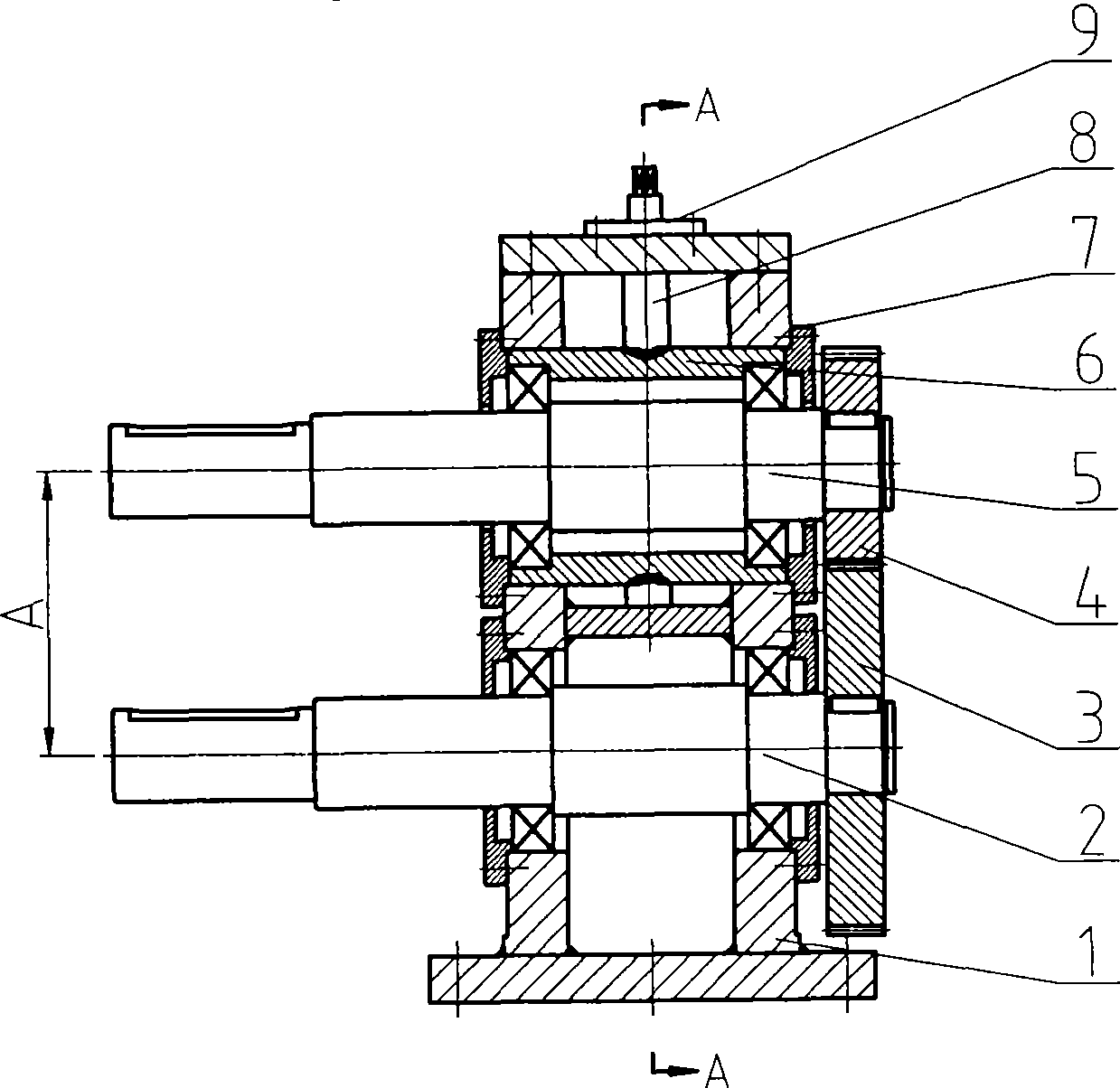
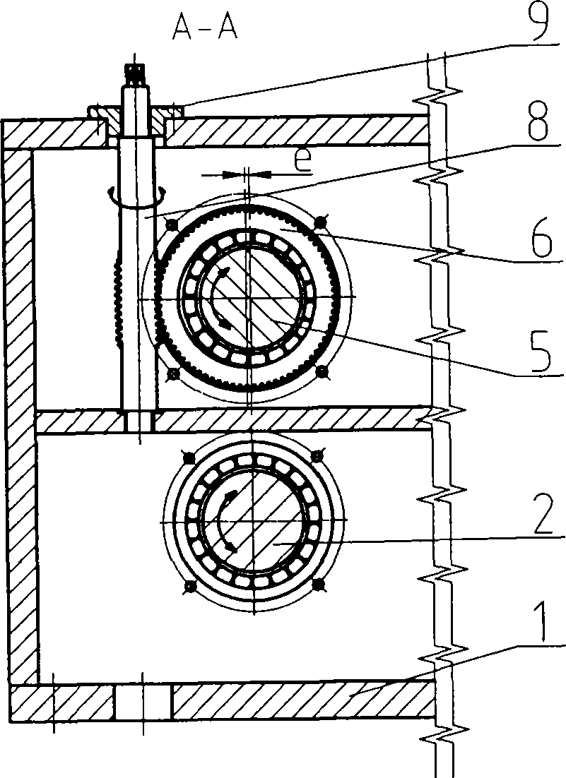
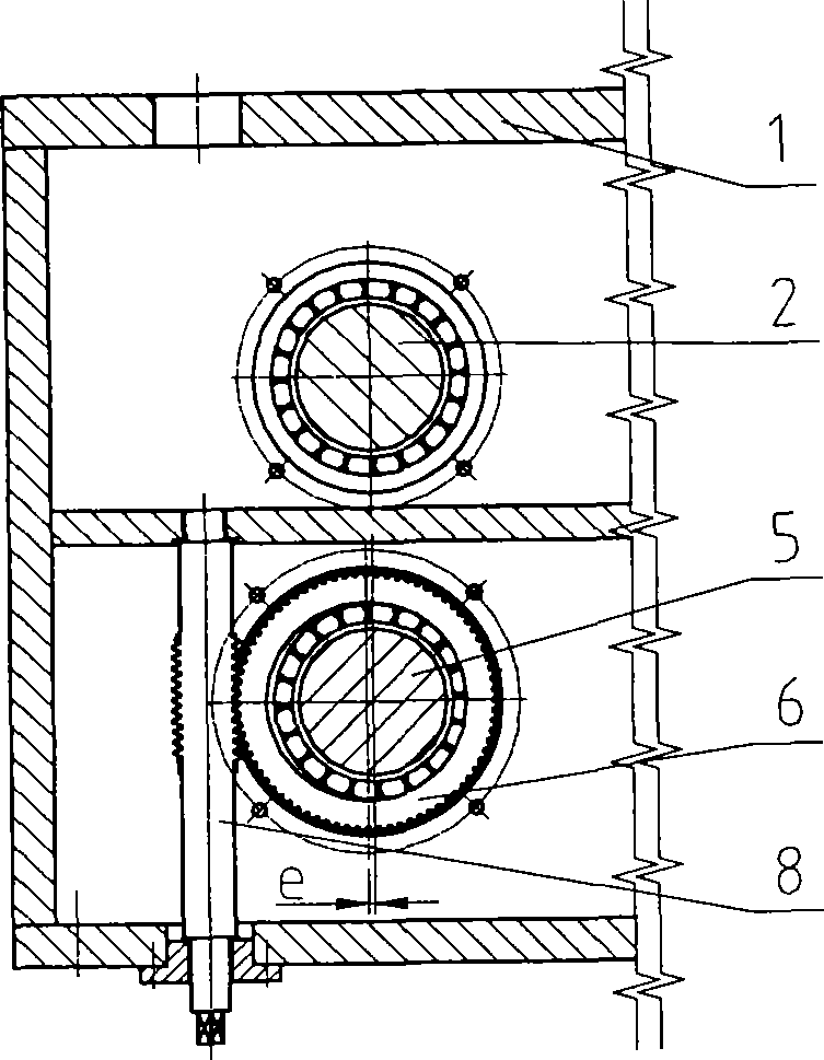
[0021] The present invention mainly consists of a frame 1, a fixed shaft 2 with a lower gear 3 on the frame 1, and an adjustment shaft 5 with an upper gear 4, an eccentric sleeve 6 sleeved on the adjustment shaft 5, and placed on the frame 1. The adjusting rod 8 with the adjusting mechanism 9 connected with the eccentric sleeve 6 is composed of end caps 7 placed at the axial ends of the eccentric sleeve 6; the bearing housing holes at the two ends of the eccentric sleeve 6 are coaxial and exist 1~1 with the outer circle of the eccentric sleeve 6 10mm eccentricity.

[0022] The specific implementation of the present invention is as follows:

[0023] As attached figure 1 with 2 As shown, when the plate thickness increases, the gap between the upper and lower shafts needs to be increased. When adjusting, the adjusting rod 8 moves upward to make the eccentric sleeve 6 rotate counterclockwise. Due to the eccentricity e, the adjusting shaft 5 moves upward, The distance A between the fi...


PUM


Abstract

A shaft distance adjusting mechanism for a steel plate forming machine belongs to the manufacturing technical field of the matched parts of machines, building material forming machines and other devices. The adjusting mechanism mainly comprises a machine frame (1), a fixed rotating shaft (2) which is arranged on the machine frame (1) and provided with a lower gear (3), an adjusting rotating shaft (5) which is also arranged on the machine frame (1) and provided with an upper gear, an eccentric sleeve (6) sleeved on the adjusting rotating shaft (5), an adjusting rod (8) arranged on the machine frame (1) and connected with the eccentric sleeve (6), and an end cover (7) arranged at two axial ends of the eccentric sleeve (6); and bearing saddle bores at both ends of the eccentric sleeve (6) share one axis, and an eccentric distance e ranging from 1 mm to 10 mm exists between the bearing saddle bores and an axle center. The shaft distance adjusting mechanism has the advantages of reasonable design of an integral structure, simple structure, stable work and convenient adjustment.

Description

Technical field [0001] The invention relates to a shaft spacing adjustment mechanism for a steel plate forming machine, and belongs to the technical field of manufacturing equipment supporting parts such as machinery and building materials forming. Background technique [0002] The working principle of adjusting the spacing between the forming wheels of the existing building material forming equipment basically follows the working mode of the current building material forming equipment, that is, by adjusting the adjustment mechanism installed on the roller axle brackets installed on both sides of the equipment, the upper or lower roller axles are moved up and down to achieve The adjustment of the distance between the upper and lower wheel axles requires frequent changes in product specifications during the actual production process, and the thickness and shape of the raw material plates are different. The fasteners must be loosened before adjustment, and tightened after adjustmen...

Claims


Application Information

Patent Timeline
IPC IPC(8): B21B31/26
Inventor 俞焕庆张鹏铭王妙娟盛小锋
Owner ZHEJIANG JINGGONG SCI & TECH
Learn More