
Parachute assembly suitable for rocket

A parachute and rocket technology, which is applied in the direction of parachute, transportation and packaging, aircraft parts, etc., can solve the problems of difficult control of parachute technical state and assembly quality, low safety and reliability of parachute opening, and increase of parachute parachute accident rate, etc. Achieve the effects of high parachute opening reliability, good safety and reliability, and improved assembly quality

Inactive Publication Date: 2009-04-15
AEROSPACE LIFE SUPPORT IND LTD
View PDF0 Cites 8 Cited by
  • Summary
  • Abstract
  • Description
  • Claims
  • Application Information

AI Technical Summary

Problems solved by technology

[0003] 1. The design of the separation mechanism between the rocket nose cone and the rocket body is relatively complicated, and its development and equipment costs are relatively high
[0004] 2. After the rocket head body is separated, the parachute will quickly deploy and decelerate the rocket nose cone, while the rocket body is still moving forward at the same speed as when the parachute was opened. It is very small, so the high-speed moving arrow will catch up with the deployed parachute and interfere with it, which will cause the parachute to fail, and its safety and parachute opening reliability are low
[0005] 3. The interface relationship between parachute-nose-cone-capsule-rocket body is relatively complicated. The parachute is usually shipped in a loose state (unpacked state), and the parachute is packaged and assembled with the rocket by a non-professional parachute manufacturer. It is so easy to cause parachute damage. The technical status and assembly quality are not easy to control, which increases the accident rate of parachute opening

Method used


Image

  • Parachute assembly suitable for rocket
  • Parachute assembly suitable for rocket
  • Parachute assembly suitable for rocket

Examples


Embodiment 1

[0036] The present invention is applicable to rocket parachute device embodiment 1 and has the following advantages:

[0037] 1. The lateral parachute opening technology better solves the defect that the axial parachute is easy to interfere in the past, and improves the reliability of the parachute.

[0038] 2. The application of lateral parachute opening technology makes the overall design and delivery of the recovery cabin possible, makes the parachute assembly quality controllable, and reduces the failure rate in use.

[0039] 3. The interface relationship between the recovery module and the rocket is simple, which is conducive to improving the interchangeability and versatility of the recovery module.

[0040] 4. Utilizing the canopy cover to pack the main parachute can effectively ensure the parachute opening procedure of the main parachute, improve the utilization rate of the parachute cabin volume, and reduce the dynamic load of parachute opening when the main parachute...


PUM


Abstract

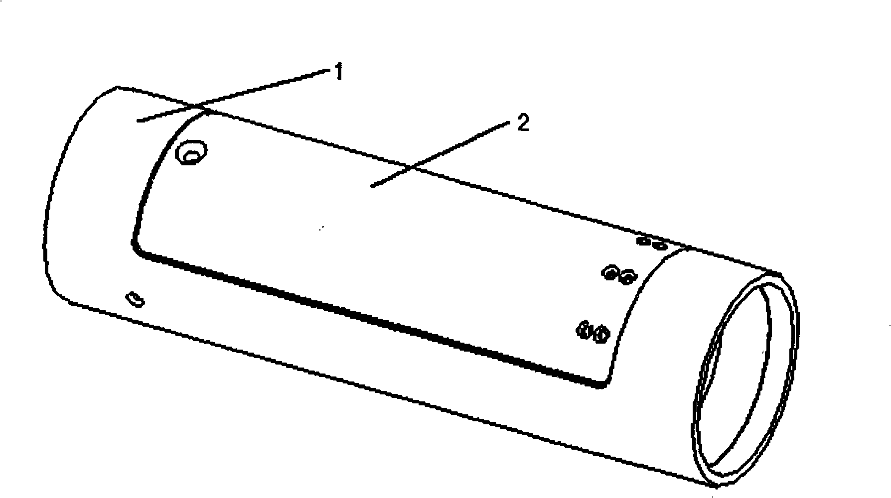
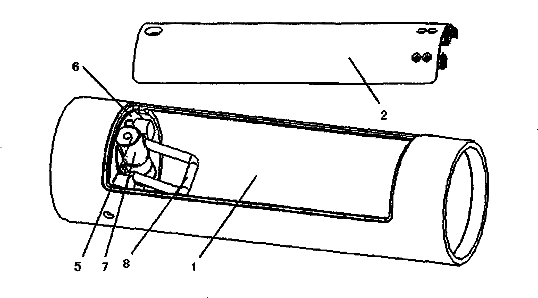
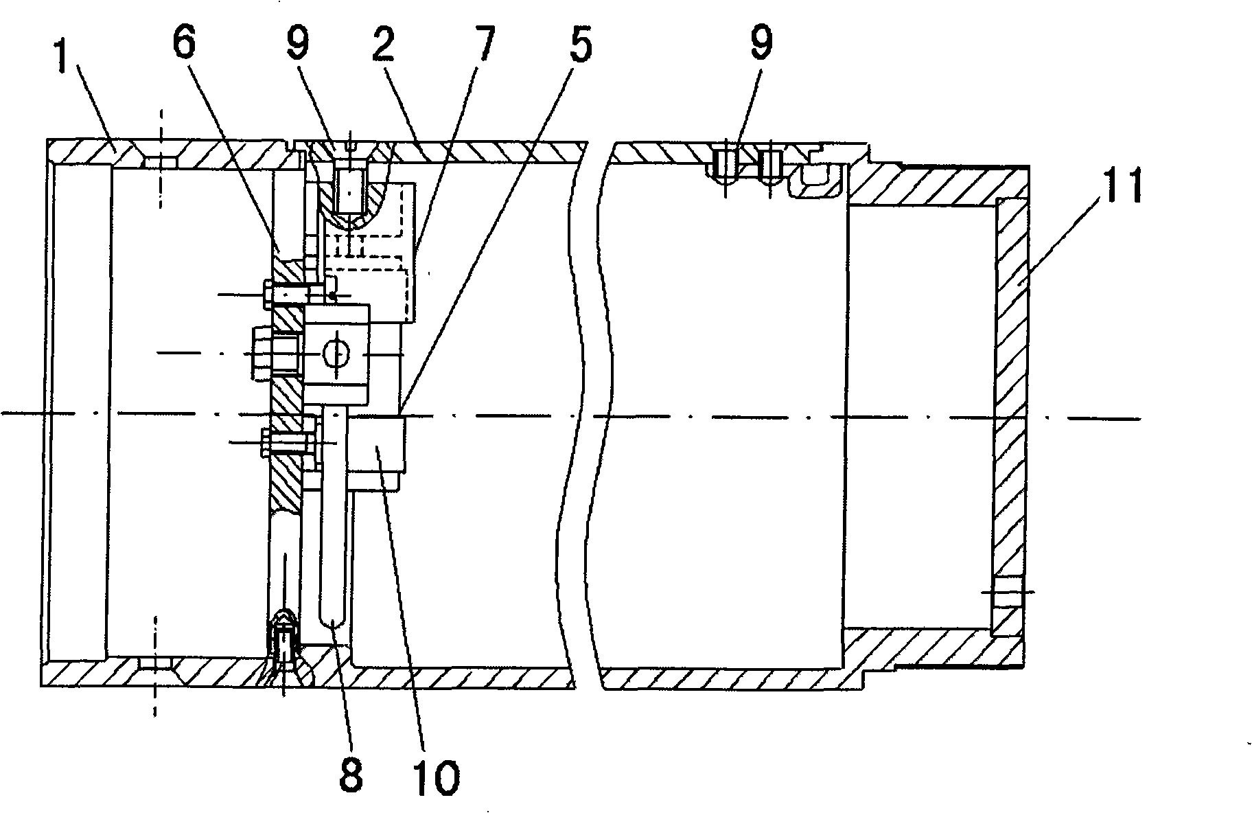
The invention relates to a parachute assembly applicable to rockets, which comprises a cylinder-shaped cabin body (1) the two ends of which are connected with other parts of a rocket; the side wall of the cabin body (1) is provided with a hatch where a hatchcover (2) and a hatchcover opening device are arranged; the hatchcover (2) is connected with a retarding parachute body through a hauling rope, the retarding parachute body is connected with a main parachute body through a retarding parachute connecting rope, and the main parachute body is connected with the cabin body (1) through a main parachute connecting belt. According to the appearance structure characteristic of a meteorocket (or a sounding rocket), in the parachute assembly, the hatch and the hatchcover thereof are arranged on the side wall of the cabin body and the parachute hatchcover is released in side direction of the cabin body, thus overcoming the defects in the prior art, without designing a rocket detaching mechanism and with simple structure and low cost; and the separated rocket body is avoided, thus causing no interference on the parachute, with good safety and reliability; and the interfaces among each part of the rocket are simple, thus improving the parachute assembly quality and reducing the using failure rate.

Description

technical field [0001] The invention relates to a parachute device, in particular to a parachute device used on a rocket used in fields such as meteorology and sounding. Background technique [0002] The process of pulling out the parachute from the rocket parachute to opening is a key technology that needs to be solved in the design of rocket parachutes used in meteorology, sounding and other fields. For meteorological rockets or sounding rockets with a cross-sectional diameter of the parachute less than 200mm, due to the high parachute opening speed (generally greater than 150m / s), the small parachute compartment and the complicated situation of the tail parachute opening channel, the separation mechanism is often used to separate the rocket The nose cone and the rocket body are pushed away at a speed of not less than 10m / s, and the parachute is opened along the rocket axis. There are following problems in this parachute technology: [0003] 1. The design of the separati...

Claims


Application Information

Patent Timeline
IPC IPC(8): B64D17/64
Inventor 王文凯刘勇蔡磊
Owner AEROSPACE LIFE SUPPORT IND LTD
Learn More