

Device for measuring laser energy of laser radar ceilometer
A technology of laser energy and measuring device, applied in the field of laser measurement, can solve problems such as unstable proportional relationship, and achieve the effect of maintaining stable proportional relationship
Inactive Publication Date: 2009-04-15
凯迈(洛阳)测控有限公司
View PDF0 Cites 2 Cited by
- Summary
- Abstract
- Description
- Claims
- Application Information
AI Technical Summary
Problems solved by technology
[0003] The object of the present invention is to provide a laser energy measurement device of a laser radar nephelograph that makes the proportional relationship between the laser energy measurement result and the energy received by the laser receiver stable when the temperature changes, so as to solve the problem caused by the central wavelength of the laser. The problem of unstable proportional relationship between the measurement result of the laser energy measuring device and the energy actually received by the laser receiver caused by drift
Method used
View moreImage
Smart ImageViewing Examples

Examples
Embodiment Construction
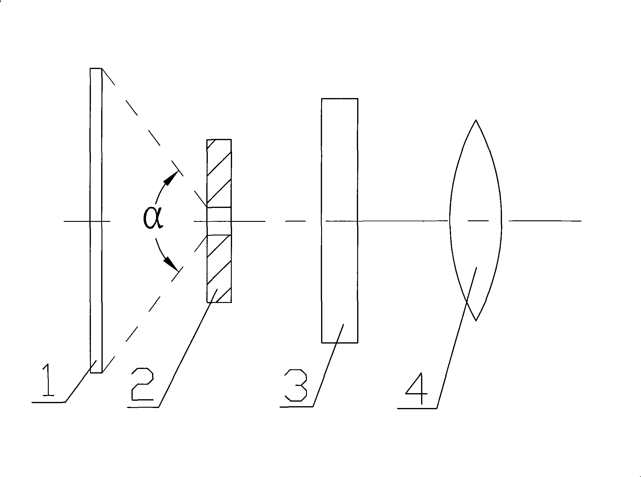
[0009] figure 1 It is a schematic diagram of the present invention, including an energy detection device 4, an aperture 2 is arranged in front of the energy detection device 4, an optical filter 3 is arranged between the aperture 2 and the energy detection device 4, and a circular frosted glass is arranged in front of the aperture 2 1. The perpendicular line passing through the center of the plane where the circular frosted glass 1 is located passes through the center of the aperture of the diaphragm 2, and the laser incident angle α formed by the ground glass 1 and the diaphragm 2 is equal to the receiving field angle of the laser receiver.
Login to View More PUM
 Abstract
The invention relates to a laser energy measurement apparatus in a laser radar ceilometer. The laser energy measurement apparatus in the laser radar ceilometer comprises an energy detection device and a diaphragm arranged in front of the energy detection device, ground glass arranged in front of the diaphragm, and an optical filter arranged between the diaphragm and the energy detection device. The apparatus is mainly used for solving the problem of unstable proportional relation between the measurement results of the laser energy measurement apparatus and the actual energy received by a laser receiver, and the problem is caused by temperature drift in the central wavelength of the laser.
Description
technical field [0001] The invention and a laser energy measuring device of a laser radar nephelograph belong to the technical field of laser measurement. Background technique [0002] At present, when laser energy measurement devices in the field of laser measurement technology measure laser energy, they generally measure directly without filter and incident angle correction; due to the temperature drift of the central wavelength of the laser, the narrowband filter used by the receiver The passband part of the light sheet is not flat, that is, the light passing rate of different wavelengths is inconsistent; if the laser energy measurement device has no filter, the proportional relationship between the energy measured by it and the energy received by the receiver varies with the temperature. The change is unstable, which affects the measurement results; in addition, the spectral characteristics of the filter for different incident angles are also inconsistent, so if the corr...
Claims
Login to View More Application Information
Patent Timeline
 Patent Type & AuthorityApplications(China)
IPC IPC(8): G01S7/497G01J1/04
Inventor滕军佟增亮肖巧景
Owner凯迈(洛阳)测控有限公司