
Stator of a rotary electric machine having secured core slot insulators

一种绝缘体、定子铁芯的技术,应用在敷设固体绝缘、绕组绝缘的形状/式样/结构、绕组导体的形状/式样/结构等方向,能够解决困难工艺等问题

Active Publication Date: 2009-04-15
REMY TECHNOLOGIES LLC
View PDF0 Cites 16 Cited by
  • Summary
  • Abstract
  • Description
  • Claims
  • Application Information

AI Technical Summary

Problems solved by technology

This might solve the slot liner problem, but disadvantageously introduces a difficult process of welding the U-shaped parts to form the coil windings

Method used


Image

  • Stator of a rotary electric machine having secured core slot insulators
  • Stator of a rotary electric machine having secured core slot insulators
  • Stator of a rotary electric machine having secured core slot insulators

Examples


Embodiment Construction

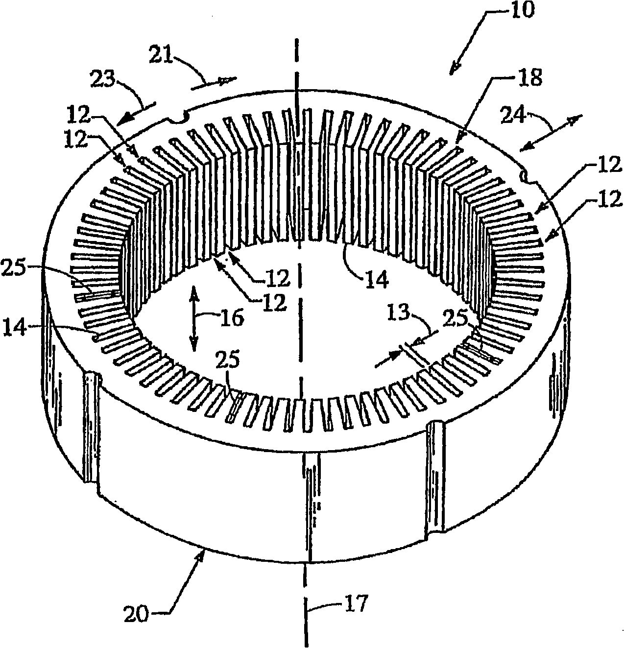
[0025] Refer to figure 1 , The generally cylindrical stator core is indicated as 10 as a whole. The stator core 10 includes a plurality of core slots 12 formed on the inner circumferential surface 14 thereof. The core slot 12 extends axially, as indicated by the arrow 16, and is parallel to the central axis 17 of the stator core 10 at the first end 18 and the second end 20 thereof. The axially upward direction is defined as the moving direction to the first end 18 of the stator core 10, and the axially downward direction is defined as the moving direction to the second end 20 of the stator core 10. Preferably, the iron core slots 12 are arranged equidistantly along the circumferential inner surface 14 of the stator iron core 10, and each inner surface 14 of the iron core slot 12 is substantially parallel to the central axis 17. The clockwise direction of the circle is shown by arrow 21, and the counterclockwise direction of the circle is shown by arrow 23.

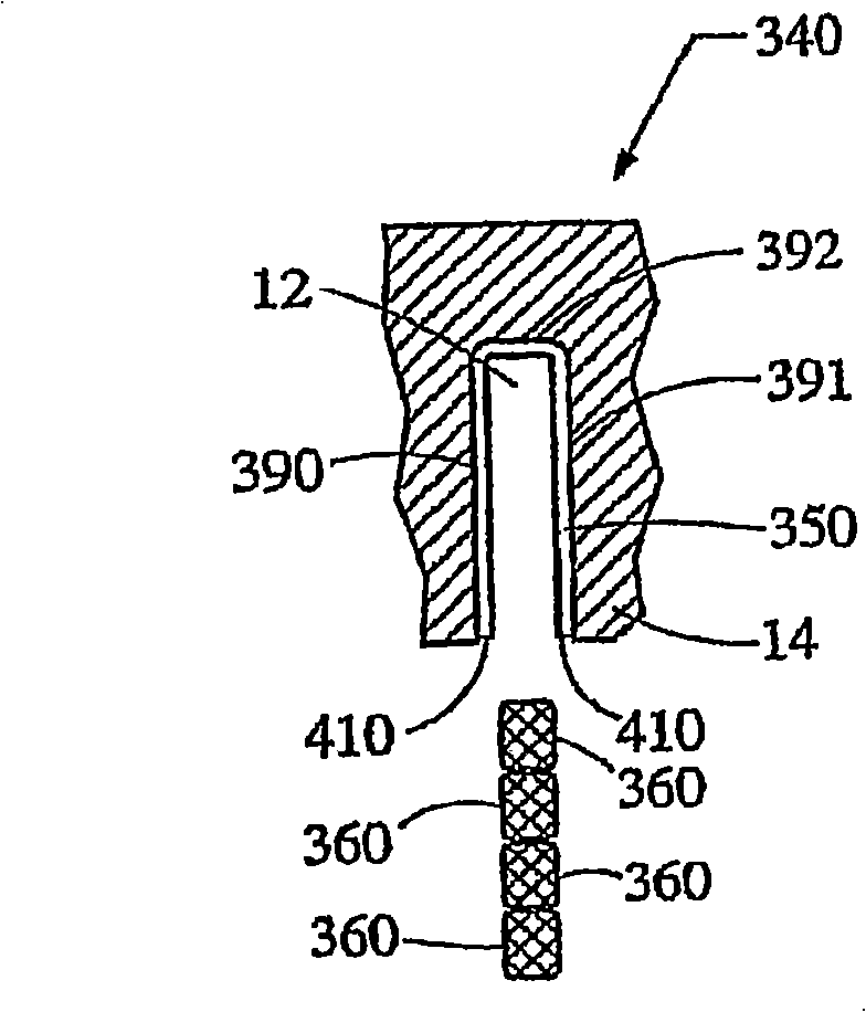
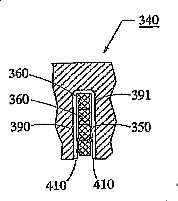
[0026] The core slot ...


PUM


Abstract

A stator of a rotary electric machine having secured core slot insulators includes a multi-phase stator winding, having a plurality of slot segments that are adapted to be radially inserted into a plurality of circumferentially spaced axially-extending core slots in a surface of a cylindrically-shaped stator core. The stator winding includes the plurality of slot segments alternately connected at the first and second ends of the stator core by a plurality of end loop segments to form the winding. The plurality of core slots house an insulator to electrically isolate the slot segments from the core slots. The insulator is secured to the sides of the core slot prior to the process of radial inserting the plurality of slot segments into the plurality of core slots of the cylindrically-shaped stator core.

Description

Background technique [0001] The present invention generally relates to an electric motor, and more particularly relates to an iron core slot insulator for an electric motor equipped with an iron core and coil windings. Electric machines, such as alternating current generators or alternators, are well known. The prior art alternator mainly includes a stator assembly and a rotor assembly located in the generator housing. The stator assembly is installed on the housing and includes a substantially cylindrical stator core, and the stator core is provided with a plurality of slots formed thereon. The rotor assembly includes a motor rotor connected to a generally cylindrical shaft, which is rotatably mounted on the housing and coaxial with the stator assembly. The stator assembly includes a number of coils wound on it and forms a winding. The stator winding is composed of a slot portion and an end coil portion. The slot portion is located in the core slot. The end coil portion connects ...

Claims


Application Information

Patent Timeline
Patent Type & Authority Applications(China)
IPC IPC(8): H02K3/34H02K15/10H02K1/16H02K3/12H02K3/28
CPCH02K3/28H02K1/16H02K3/12H02K3/345H02K15/10Y10T29/49011Y10T29/49009Y10T29/49012Y10T29/53143
Inventor 柯克·尼特
Owner REMY TECHNOLOGIES LLC
Learn More