Anastomat

A stapler and body technology, applied in the field of staplers, can solve problems such as operation failures and accidents

Inactive Publication Date: 2009-04-22
周明喜
View PDF0 Cites 3 Cited by
  • Summary
  • Abstract
  • Description
  • Claims
  • Application Information

AI Technical Summary

Problems solved by technology

There is no empty staple cartridge locking device in the general stapler. After the suturing is completed, there is no staple in t

Method used


Image

  • Anastomat
  • Anastomat
  • Anastomat

Examples


Embodiment Construction

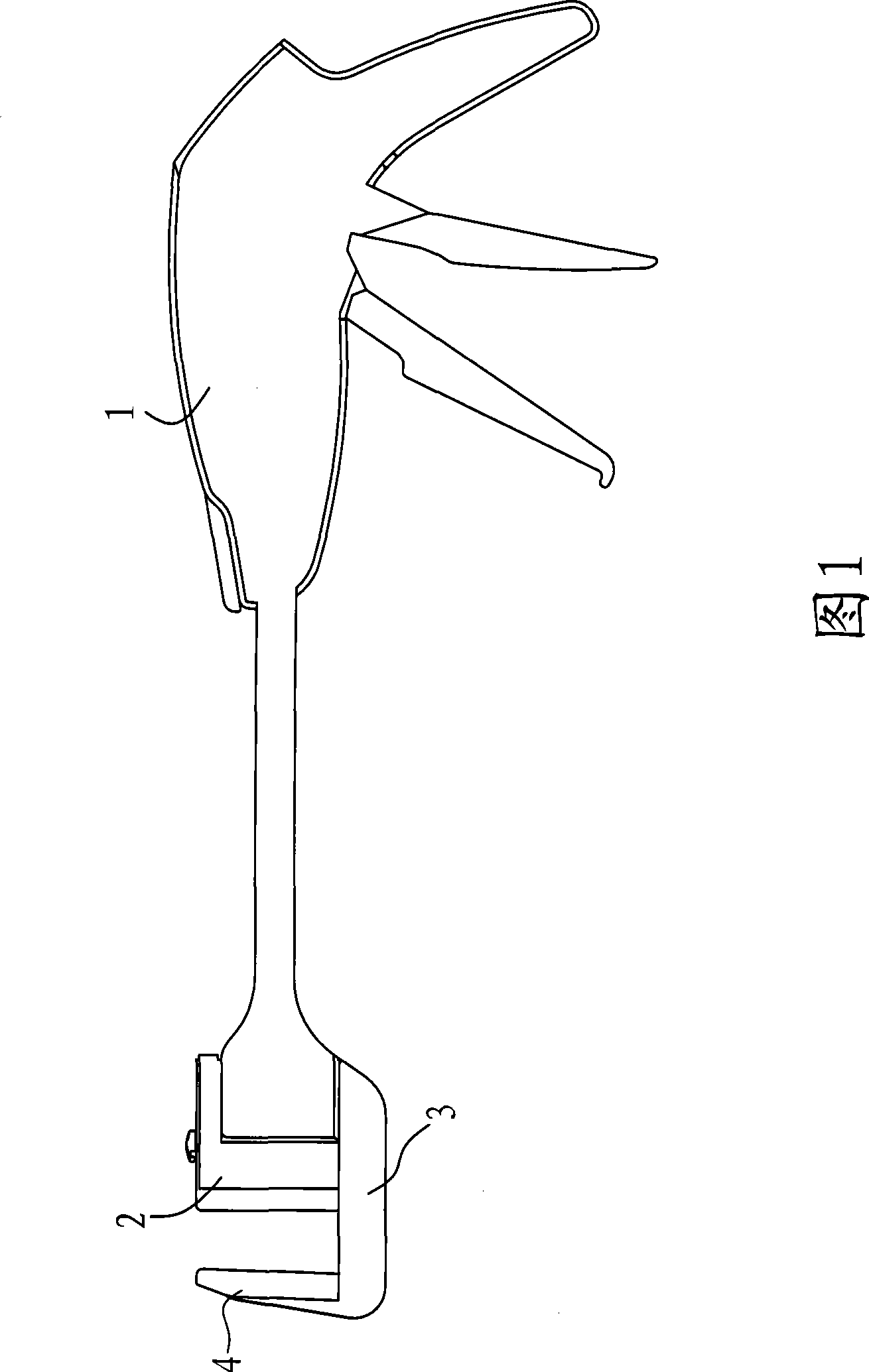
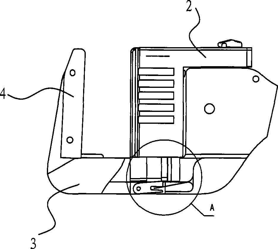
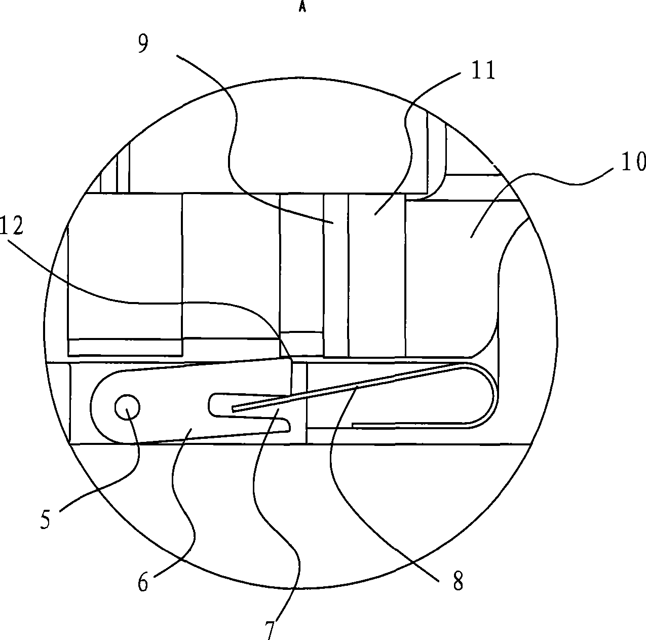
[0016] As shown in Figure 1, a stapler includes a main body 1, a staple cartridge 2 disposed on the main body 1, a nail pusher 9 disposed inside the staple cartridge 2, and a staple pusher 9 disposed on the body 1 for pushing the staple pusher 9. In this embodiment, the front end of the main body 1 is fixedly connected with a staple cartridge base 3, the staple cartridge 2 and the nail abutment seat 4 are all arranged on the staple cartridge base 4, and the front end of the push rod 10 has a nail pushing plate 9 The pushing part 11 that is in contact, in order to make the empty staple bin can be locked after suturing, the lower end surface of the pushing part 11 in the present invention is flush with the lower end surface of the nail pushing piece 9, and a stopper is pressed below the nail pushing piece 9 Block 6, the block 6 is connected with a reset mechanism that makes it pop up.

[0017] In order to save space in the staple cartridge 2, in this embodiment, a groove 7 is pr...


PUM


Abstract

The invention relates to an anastomat, which comprises a body, a pin bin which is arranged on the body, a pin pushing plate which is arranged inside the pin bin, and a push rod which is arranged on the body and used for pushing the pin pushing plate, wherein the front end of the push rod is provided with a push part which contacts the pin pushing plate; the lower end face of the push part is flush with the lower end face of the pin pushing plate; and a limit stop is pressed below the pin pushing plate and connected with a reset mechanism which drives the limit stop to upspring. After the suturing process is over each time, the push rod can be retracted, the pin pushing plate is rested on the front of the pin bin, and the limit stop upsprings under the action of the reset mechanism and prevents the push rod from pushing the pin pushing plate to suture again, so that the anastomat has the function of locking the hollow pin bin and surgical failure can not be caused due to reutilization of the hollow pin bin.

Description

technical field [0001] The invention relates to a stapler for surgery. Background technique [0002] Staplers are widely used in low rectal resection surgery, which makes the operation safer. There is no empty staple cartridge locking device in the general stapler, and there is no staple in the staple cartridge after suturing, which may be operated due to negligence, so that the operation fails and unnecessary accidents are caused. Contents of the invention [0003] The purpose of the present invention is to provide a stapler. When the staple cartridge is empty, the instrument is locked and cannot be operated. [0004] In order to achieve above object, the scheme that the present invention adopts is: [0005] A stapler, comprising a body, a staple cartridge arranged on the body, a nail pusher disposed inside the staple cartridge, a push rod disposed on the body for pushing the staple pusher, the The front end of the push rod has a pushing part in contact with the nail p...

Claims


Application Information

Patent Timeline
IPC IPC(8): A61B17/115A61B17/068A61B17/138
Inventor 周明喜
Owner 周明喜
Why Eureka
Try Eureka