Equipment wire clamp anti-breaking device

An equipment clamp and anti-break technology, which is applied to the coupling device, the device for reducing the stress at the connection point of the wire, and the parts of the connection device, etc., can solve the problem of corrosion, burnout of the equipment clamp, and unstable operation of the 10kV power distribution network. problem, achieve the effect of preventing breakage

Active Publication Date: 2020-08-07
GUIZHOU POWER GRID CO LTD
View PDF6 Cites 6 Cited by
  • Summary
  • Abstract
  • Description
  • Claims
  • Application Information

AI Technical Summary

Problems solved by technology

In the daily distribution network lines, the tension clamps, equipment clamps, hugging clamps, etc. in the distribution lines are exposed to the atmosphere for a long time and undertake the task of transmitting current. Significantly, the wind blows the wires to swing, loosens the connection between the wires and the clamps, and causes 10kV distribution lines (switches, knife switches) and distribution transformer pile heads and equipment clamps installed on the upper end of the distribution transformer to burn out frequently, resulting in 10kV The power distribution network is not running smoothly

Method used


Image

  • Equipment wire clamp anti-breaking device
  • Equipment wire clamp anti-breaking device
  • Equipment wire clamp anti-breaking device

Examples


Embodiment 1

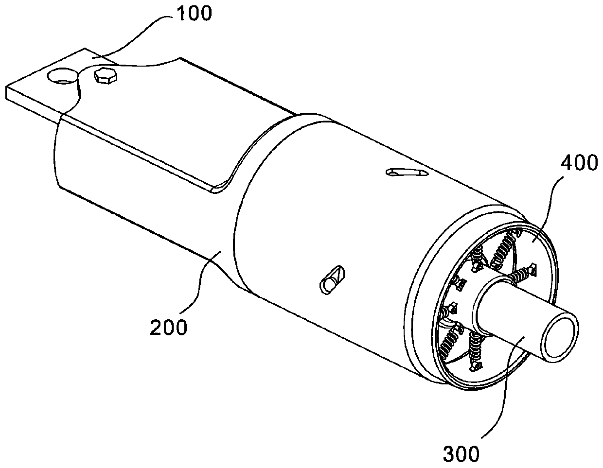
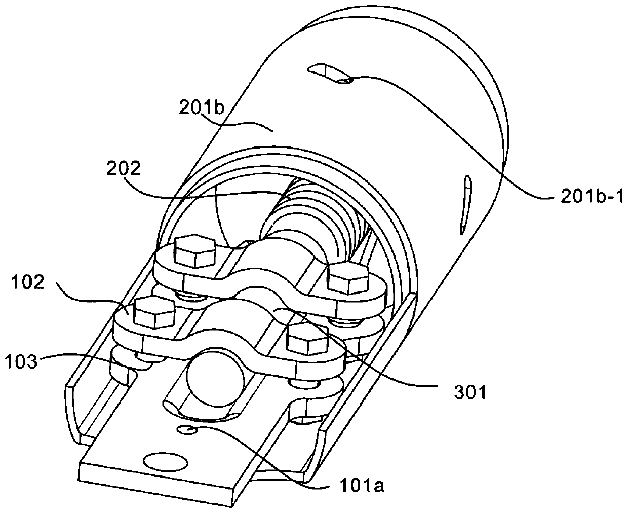
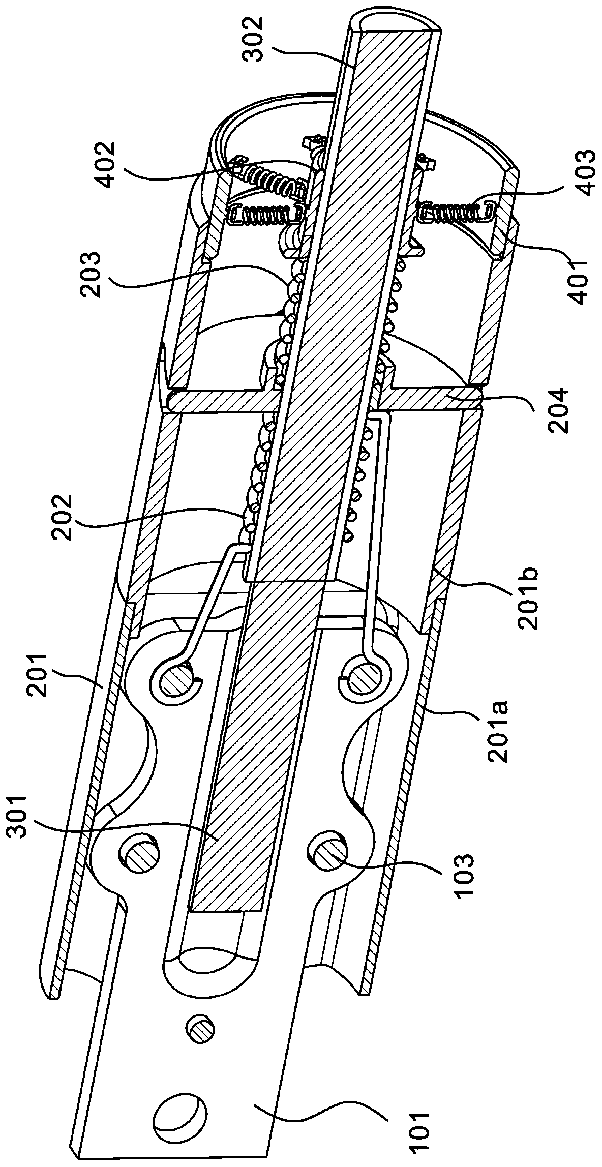
[0032] refer to Figure 1-7 , the present embodiment provides an equipment line clip anti-breakage device, including an equipment line clamp 100, including an outgoing line terminal 101, a clamping piece 102 connected to the outgoing line terminal 101, and a bolt 103, and the bolt 103 fastens the clamping piece 102 to the On the outgoing line terminal 101, the outgoing line terminal 101 is a conductor, which is drawn out from the power equipment and connected with the external wire. The clamping piece 102 is used to fasten the lead on the outgoing line terminal 101 and fastened by the bolt 103 to prevent falling off; anti-breakage The unit 200 includes a box body 201 sleeved on the equipment clamp 100, a first spring 202 and a second spring 203 connected to the bolt 103, a spring seat 204 is arranged between the first spring 202 and the second spring 203, and the spring The seat 204 is located in the box body 201. The winding direction of the first spring 202 and the second sp...

Embodiment 2

[0041] refer to Figure 1-7 , is the second embodiment of the present invention, this embodiment is based on the previous embodiment, and the difference from the previous embodiment is: the outlet terminal 101 is provided with a fixing hole 101a, and one end of the first box body 201a is provided with a positioning end 201a -1, the positioning end 201a-1 is connected to the fixing hole 101a through the fixing bolt 205 .

[0042] Specifically, the equipment clamp 100 includes an outgoing line terminal 101, a clamping piece 102 connected to the outgoing line terminal 101, and a bolt 103. The bolt 103 fastens the clamping piece 102 to the outgoing line terminal 101. The outgoing line terminal 101 is a conductor, and the The equipment lead is connected with the external wire, and the clamping piece 102 is used to fasten the wire on the outlet terminal 101 and fasten it through the bolt 103 to prevent it from falling off; The box body 201, the first spring 202 and the second sprin...


PUM


Abstract

The invention discloses an equipment wire clamp anti-breaking device which comprises a wire outlet terminal, a clamping sheet connected with the wire outlet terminal, and a bolt, and the clamping sheet is fastened on the wire outlet terminal by the bolt; and the device further comprises an anti-breaking unit and a cable. The anti-breaking unit comprises a box body arranged on an equipment wire clamp in a sleeving mode, a first spring and a second spring, the first spring and the second spring are connected with the bolt, a spring seat is arranged between the first spring and the second spring,the spring seat is located in the box body, the winding directions of the first spring and the second spring are opposite, and the number of turns of the first spring and the second spring is the same; the cable comprises an insulating layer and a cable core, and the insulating layer is sleeved with the first spring and the second spring. According to the device, when the equipment wire clamp andthe cable are subjected to the swinging external force, the multiple symmetrically-arranged springs limit the movement range of the cable and absorb the external force, and the cable is prevented from being broken.

Description

technical field [0001] The invention relates to the field of electric power safety, in particular to an anti-breakage device for wire clips of equipment. Background technique [0002] Wire clamps are iron or aluminum metal accessories that can be fixed on the wires. Most of them need to bear a large pulling force during operation, and some also need to ensure good electrical contact at the same time. Equipment clamps are mainly used to connect the down conductors of substation busbars with the outlet terminals of electrical equipment (such as transformers, circuit breakers, isolation openings, wall bushings, etc.), because the outlet terminals of common electrical equipment are made of copper and aluminum. Two types, and the bus lead-out wires are divided into aluminum hinged wires and steel-cored aluminum stranded wires, so the equipment clamps are divided into two series of aluminum equipment wire flats and copper-aluminum transition equipment wire clamps in terms of mater...

Claims


Application Information

Patent Timeline
Patent Type & Authority Applications(China)
IPC IPC(8): H01R13/585H01R13/58H01R13/56
CPCH01R13/562H01R13/5812H01R13/585
Inventor 陆韦刚肖远奇王有军刘坤李义岳廷学刘庆国孙胜宋建
Owner GUIZHOU POWER GRID CO LTD
Why Eureka
Try Eureka