
Gas making compound combustion chain furnace

A chain furnace and chain grate technology are applied in the field of chain grate gas composite combustion chain furnace, which can solve the problems of low combustion intensity and combustion efficiency of chain grate, difficulty in adapting to volatile matter, and inability to catch fire immediately, and achieve gas blackness. The effect of stable compliance, intensified combustion in the furnace, and improved thermal efficiency

Inactive Publication Date: 2013-04-03
河北华林机械设备有限公司
View PDF5 Cites 0 Cited by
  • Summary
  • Abstract
  • Description
  • Claims
  • Application Information

AI Technical Summary

Problems solved by technology

Its inherent disadvantage is that the coal cannot be ignited immediately after entering the furnace, and it needs to go through a long drying and preheating process. The heat required for drying, preheating and subsequent ignition comes from the flames that have already burned in the furnace and the front and rear arches of the refractory materials that have been roasted red. For radiant heat, coal can only be guided from the upper surface of the coal seam first, and the drawn flame will gradually spread to the bottom of the coal seam, while the air required for combustion is sent upward from the bottom. This kind of reverse propagation of flame and air is not conducive to combustion. , so the combustion intensity and combustion efficiency of the chain grate are low, and it is difficult to adapt to the coal with low volatile content, high moisture or ash content

Method used


Image

  • Gas making compound combustion chain furnace

Examples


Embodiment Construction

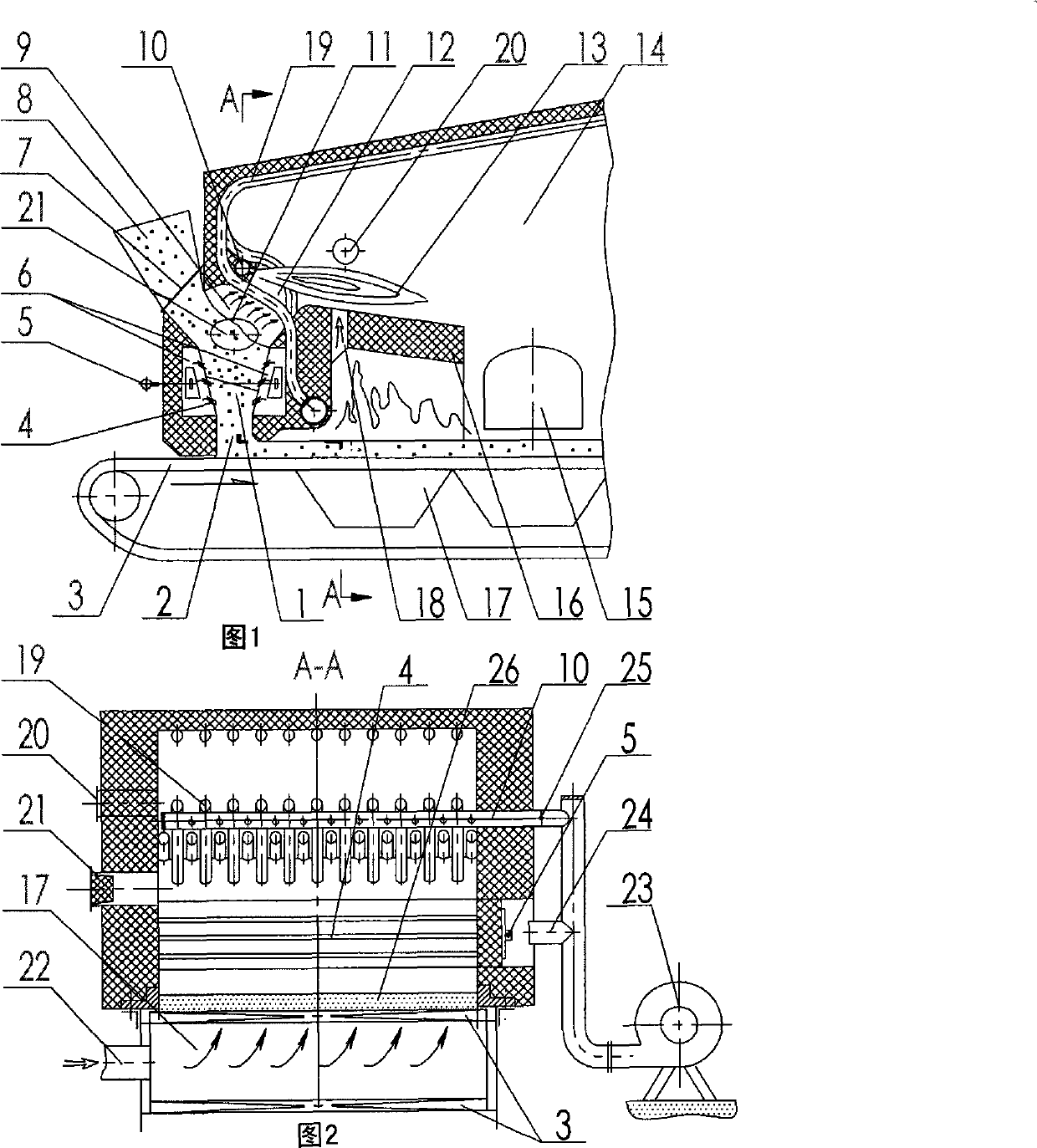
[0013] as attached figure 1 As shown, the present invention is provided with a front pre-combustion vertical furnace 1 at the front end of the chain grate 3, and an air chamber 6 with an air outlet 4 is arranged on both sides of its inner wall, and the upper end of the front pre-combustion vertical furnace 1 There is a coal-fired inlet 7 connected to the coal hopper 8, and the other end is provided with a gas outlet 12 connected to the chain furnace hearth 14, and the lower part of the pre-combustion vertical furnace 1 has a coal outlet 2 connected to the chain grate 3, In the gas chamber 9, there is an ejector air pipe 10, and at the front end of the chain furnace hearth 14, there is a downward-inclined front arch 16 and a gas ignition port 18 for enhanced combustion, and the front vertical furnace blower 23 is connected to the ejector air pipe 10. pass, as attached figure 2 As shown, the front vertical furnace blower 23 communicates with the air chamber 6 through the air c...


PUM


Abstract

The invention relates a gas making compound combustion chain furnace; a preposing preburning vertical furnace is arranged at the front end of a chain grate, the two sides of the inner wall of the vertical furnace are provided with wind chambers provided with air outlets; a fire coal inlet which is arranged at one end of the upper part of the preposing preburning vertical furnace is connected witha coal supply scuttle, and the other end of the upper part of the vertical furnace is provided with a coal gas outlet that is communicated with a grate-fired furnace; the lower part of the preposing preburning vertical furnace is provided with a coal outlet which is communicated with the chain grate; a gas chamber is internally provided with an induction air duct, the front end of the grate-firedfurnace is provided with a declinate face arch used for supplemental firing and a gas lighting-up tuyere, and the preposing preburning vertical furnace is arranged in the front of the chain grate; the coal is on fire to burn in advance in the preposing preburning vertical furnace, and coal gas is generated in a following way, so that furnace combustion is greatly strengthened, and the flying ash quantity is further reduced, thus not only maintaining the advantages of the combustion of the chain grate, but also thoroughly overcoming the inherent disadvantages of the combustion of the chain grate.

Description

technical field [0001] The invention relates to a chain grate gas composite combustion chain furnace with the function of self-made gas. technical background [0002] Chain grate combustion is the most widely used combustion technology for coal-fired industrial boilers and industrial kilns. Its advantages are simple system, reliable operation, low operating power consumption, and the proportion of fly ash is higher than that of coal powder, coal-water slurry, and circulating fluidized bed. The combustion is much smaller, the cost of flue gas purification is low, and the ash is easy to handle. It is more suitable for the small and scattered characteristics of industrial boilers and industrial kilns. Coal-fired industrial boilers in all countries in the world are mainly chain boilers. Its inherent disadvantage is that the coal cannot be ignited immediately after entering the furnace, and it needs to go through a long drying and preheating process. The heat required for drying,...

Claims


Application Information

Patent Timeline
Patent Type & Authority Patents(China)
IPC IPC(8): F23B10/02F23B30/08
Inventor 陈善军赖光楷石爱敏刘英
Owner 河北华林机械设备有限公司
Learn More