Pad structure body for accelerator padel

A technology for accelerator pedals and structures, applied to the layout of power plant control mechanisms, transportation and packaging, and vehicle parts, to achieve the effects of ensuring impact resistance, easy and reliable assembly, and ensuring basic strength

Active Publication Date: 2012-04-04
F TECH INC +1
View PDF1 Cites 0 Cited by
  • Summary
  • Abstract
  • Description
  • Claims
  • Application Information

AI Technical Summary

Problems solved by technology

[0006] However, in the structure proposed in Patent Document 1, although excellent functionality and mass productivity are achieved by integrally molding the pad, the hinge portion, and the stopper fitting portion in the pad portion of the accelerator pedal using one resin material, However, under the various vehicle design environments in recent years, a higher degree of design freedom is sometimes required

Method used


Image

  • Pad structure body for accelerator padel
  • Pad structure body for accelerator padel
  • Pad structure body for accelerator padel

Examples


Embodiment Construction

[0110] Hereinafter, the accelerator pedal pad structure in the embodiment of the present invention will be described in detail with reference to the drawings as appropriate. In addition, in the drawing, the x-axis, y-axis, and z-axis form a three-axis orthogonal coordinate system.

[0111] First, refer to Figure 1 to Figure 6 The accelerator pad structure according to this embodiment will be described in detail.

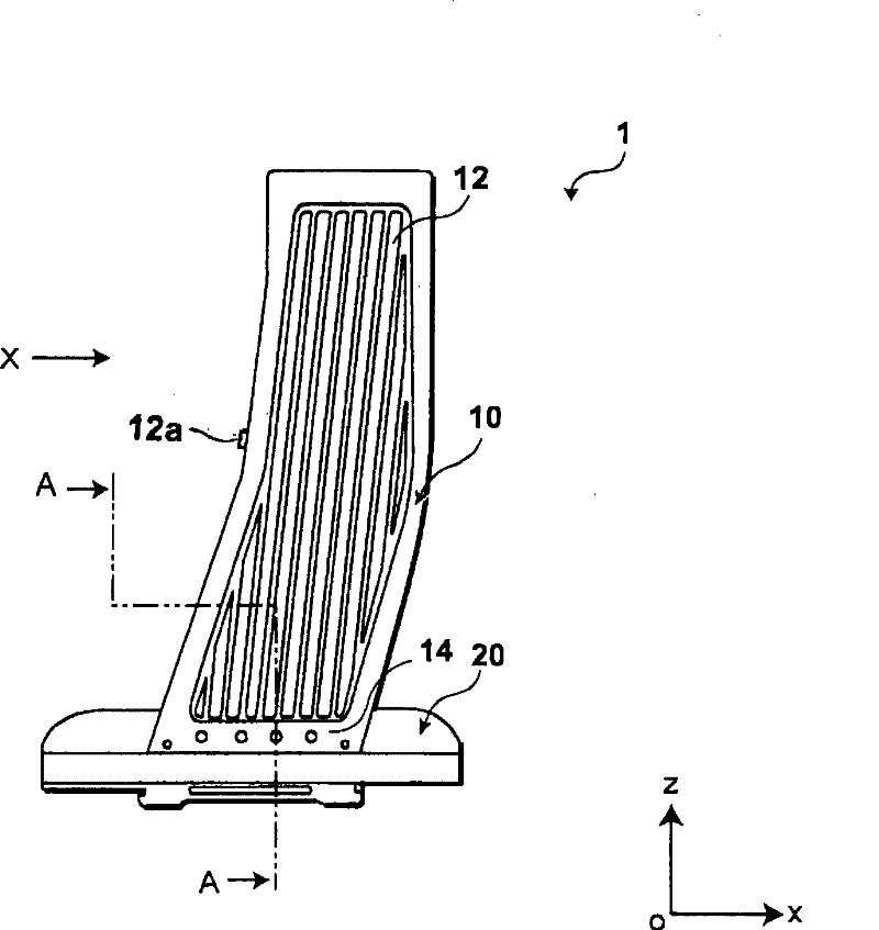
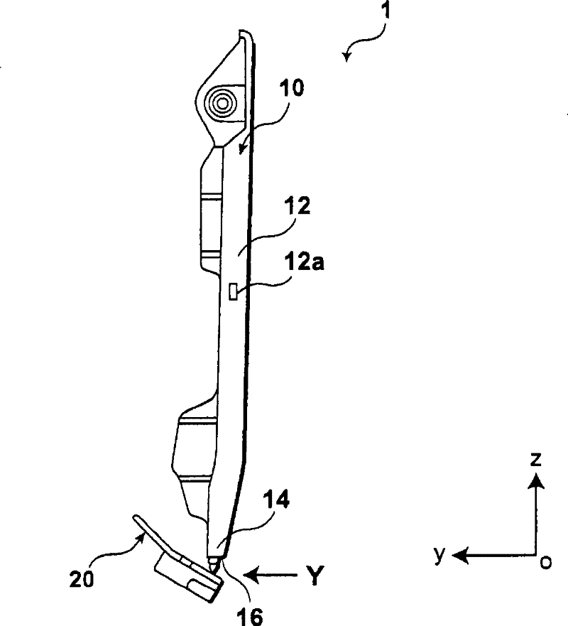
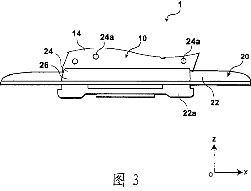
[0112] figure 1 It is a front view of the accelerator pedal pad structure of this embodiment, figure 2 is along figure 1 The graph observed in the direction of the X arrow, image 3 is along figure 2 The local enlarged view observed in the direction of the Y arrow, Figure 4 is along figure 1 An enlarged view of the partial section of the A-A line. and, Figure 5 is a front view of the hinge member of the accelerator pedal pad structure according to this embodiment, using the image 3 The same positional relationship is represented. and, Image 6 is al...


PUM


Abstract

This invention provides a pad structure body for accelerator pedal, which is capable of guaranteeing the necessary function, intensity and durability with simple and light structure and is help for improving the appearance and the visual confirmation, and excellent adequacy when mass produced. In the pad structure body for accelerator pedal, an articulated component uses first resin material to form and have: a base part connected to the vehicle body side, a connecting part at the articulated component side, and an articulated part which is rotatably and freely connected with the base part and the connecting part at the articulated component side; the pad component uses a second resin which has different formed resin hardness when compared with the first resin material to form and have: a partial pad part for performing the pedalling operation, a connecting part at the pad component side. One of the connecting part at the articulated component side and the connecting part at the pad component side covers the part with a plurality of the convex parts or the concave parts of the other one from the outer side and accommodates the parts in the inner. A machine locking part is formed when a fusion fixing part is formed so as to mutual fuse and fix.

Description

technical field [0001] The present invention relates to a pad structure for an accelerator pedal, and more particularly, to a pad structure for an accelerator pedal including a pad member for a driver's pedaling operation and a hinge member for rotatably connecting the pad member to a vehicle body side. Background technique [0002] In recent years, it has been proposed to apply resin materials such as engineering resins, which are light in weight and highly suitable for mass production, to accelerator pedal pad structures of vehicles such as automobiles. [0003] In the above-mentioned structure, since the accelerator pedal pad structure is a part for the driver of the vehicle to step on, it is necessary to ensure not only the optimal human-machine interface during normal operation, but also to ensure sufficient static pressure during emergency operation. strength, and durability for repeated operations over the life of the vehicle. On the other hand, since automobiles and...

Claims


Application Information

Patent Timeline
Patent Type & Authority Patents(China)
IPC IPC(8): B60K26/02
Inventor 加藤辉男中仓幸光萩原孝行小林正人宿利英正樱庭智裕根布谷秀人
Owner F TECH INC
Why Eureka
Try Eureka