Pretensioned prestressing composite girder and method for producing the same

A production method, pretensioning technology, applied in the processing of building materials, structural elements, building components, etc., can solve the problems of high cost, poor seismic performance, inability to pass through pipelines, etc., to reduce building height and vibration comfort Good, the effect of speeding up the construction progress

Active Publication Date: 2009-04-29
杨峰
View PDF1 Cites 19 Cited by
  • Summary
  • Abstract
  • Description
  • Claims
  • Application Information

AI Technical Summary

Problems solved by technology

[0003] The problems to be solved by the present invention are: known post-tensioned reinforced concrete beams have complicated construction technology and high cost; Large, high cost; and the known composite beam manufacturing process is more complicated, the overall cost is higher, and the pipeline cannot be passed through the beam; for this reason, the pretensioned prestressed composite beam of the present invention and its manufacturing method are provided. The present invention has a reasonable structure and a manufacturing process Simple, low cost, can also reduce the building height, can be widely used in large-span factory buildings, warehouses, markets, office buildings and urban bridges

Method used


Image

  • Pretensioned prestressing composite girder and method for producing the same
  • Pretensioned prestressing composite girder and method for producing the same
  • Pretensioned prestressing composite girder and method for producing the same

Examples


Embodiment Construction

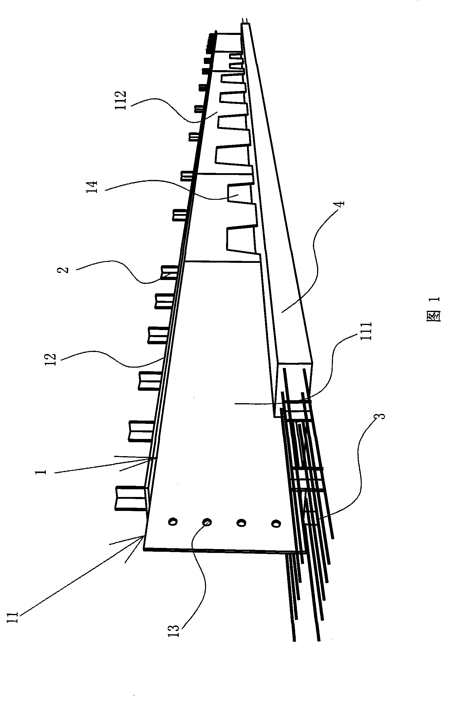
[0039] 1. Pretensioned prestressed composite beam

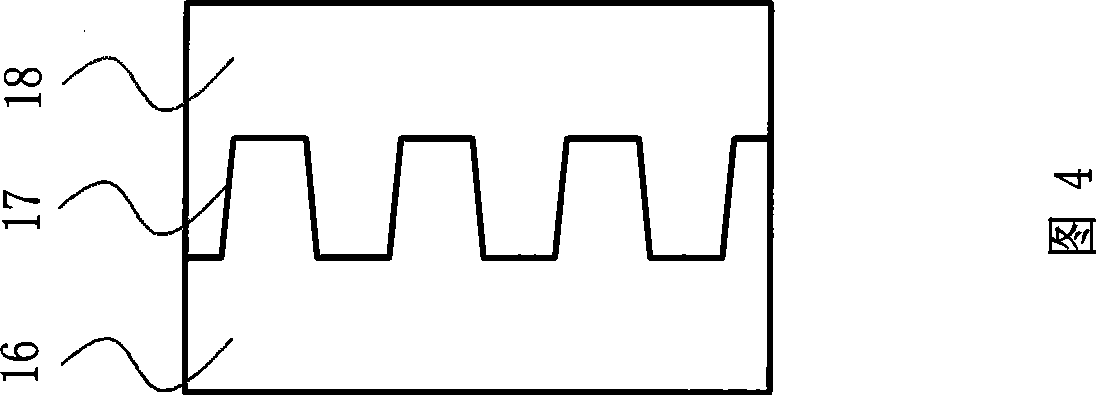
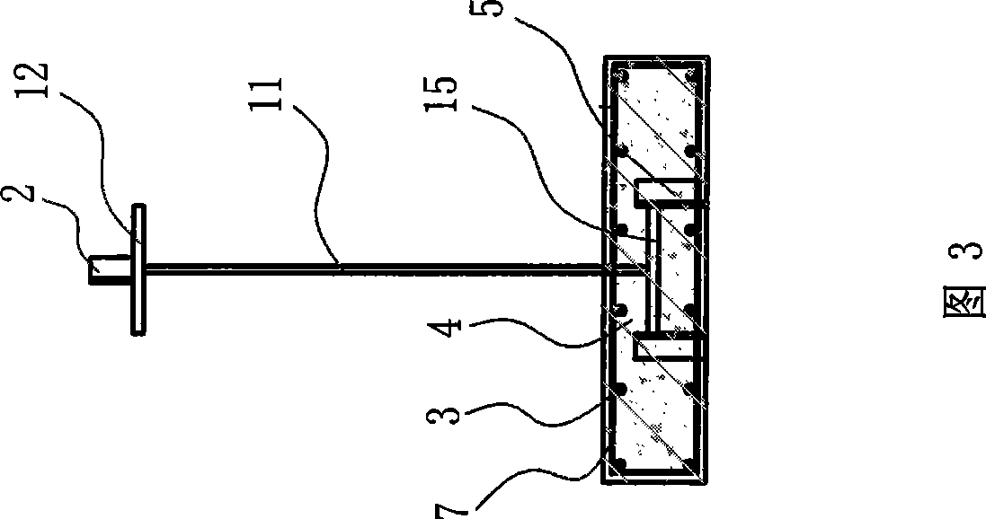
[0040] The pretensioned prestressed composite beam is an I-shaped beam composed of H-shaped steel 1 and concrete. The web 11 of the H-shaped steel is provided with trapezoidal holes 14 at intervals, and the size of several trapezoidal holes in the middle of the web is relatively large. Several trapezoidal holes on both sides of these trapezoidal holes are relatively small in size, bolt holes 13 are opened at both ends of the web, and shear nails are welded on the upper and lower flanges of the H-shaped steel. The shear nails are angle steel and channel steel. Or studs, the lower flange 15 of the H-shaped steel is surrounded by concrete to form a steel-concrete lower flange 4, the steel-concrete lower flange is a steel-concrete lower flange with a rectangular or polygonal cross section, and the steel-concrete lower flange Prestressed steel strands 3 are buried in the pretensioning method, and the two ends of the steel strands ...


PUM


Abstract

Provided is a pre-tensioned prestressed composite beam, which is an I-shaped beam composed of H-shaped steel and concrete, the web plate of the H-shaped steel is provided with trapezoidal holes (14) at intervals, the upper flange and the lower flange of the H-shaped steel are welded with shearing nails, the outer periphery of the lower flange is enclosed with concrete to form a steel-concrete lower flange (4), and the inside of the steel-concrete lower flange is embedded with prestressed steel twisted wire by pretensioning method. The manufacturing method of the composite beam is that: a steel plate is cut into two tooth-shaped plates along tooth-shaped line to be respectively as the trapezoidal hole plates of the H-shaped steel flange, the trapezoidal hole plates are welded with steel plates to form the web plate, the web plate is welded with the upper flange and the lower flange to form the H-shaped steel (1) having trapezoidal holes, the H-shaped steel is put on a base surface with the lower flange downward, the two sides of the lower flange are provided with side molds, a stirrup (7) is arranged and steel twisted wires (3) are longitudinally fastened between the two side molds, the steel twisted wire is tensioned to tensioning state, the concrete for enclosing the H-shaped lower flange is poured and tamped between the two side molds, the steel-concrete lower flange (4) is formed after demolding, and the steel twisted wire at tensioning state is loosened after the concrete reached to predetermined strength and is cut off at predetermined position. The invention is suitable for beams of buildings.

Description

technical field [0001] The invention relates to a beam of a building and a manufacturing method thereof, in particular to a steel-concrete composite beam and a manufacturing method thereof. Background technique [0002] The beams of long-span and heavy-loaded floors usually adopt prestressed reinforced concrete beams or steel-concrete composite beams. For prestressed reinforced concrete beams, if the post-tensioning process is adopted, the concrete beams must be constructed by cast-in-place construction, which has high costs and complicated processes; The anti-seismic performance is poor; while ordinary steel-concrete composite beams meet the strength and deflection requirements, the steel consumption of H steel is large and the cost is high. The composite beam disclosed by Publication No. CN 101080534A adopts the post-tensioning process, the casing is embedded in the concrete, and a specially designed prestressed tendon anchor assembly is required. In addition, the height...

Claims


Application Information

Patent Timeline
Patent Type & Authority Applications(China)
IPC IPC(8): E04C3/293E04G21/12
Inventor 杨峰
Owner 杨峰
Why Eureka
Try Eureka