Pressure detecting sensor

A technology for detecting sensors and pressure, applied in the field of sensors, can solve the problems of high temperature compensation and circuit requirements, complex structure, difficult processing, etc., to achieve the effect of improving reliability and low cost

Inactive Publication Date: 2009-04-29
江苏晶石科技集团有限公司
View PDF0 Cites 14 Cited by
  • Summary
  • Abstract
  • Description
  • Claims
  • Application Information

AI Technical Summary

Problems solved by technology

Traditional pressure detection devices include silicon piezoresistive pressure sensors, ceramic pressure sensors or capacitive pressure sensors. The common characteristics of these sensors are: relatively complex structure, difficult to process, relatively high requirements for temperature compensation and circuits, resulting in cost Relatively high, usually hundreds to thousands of yuan each

Method used


Image

  • Pressure detecting sensor

Examples


Embodiment Construction

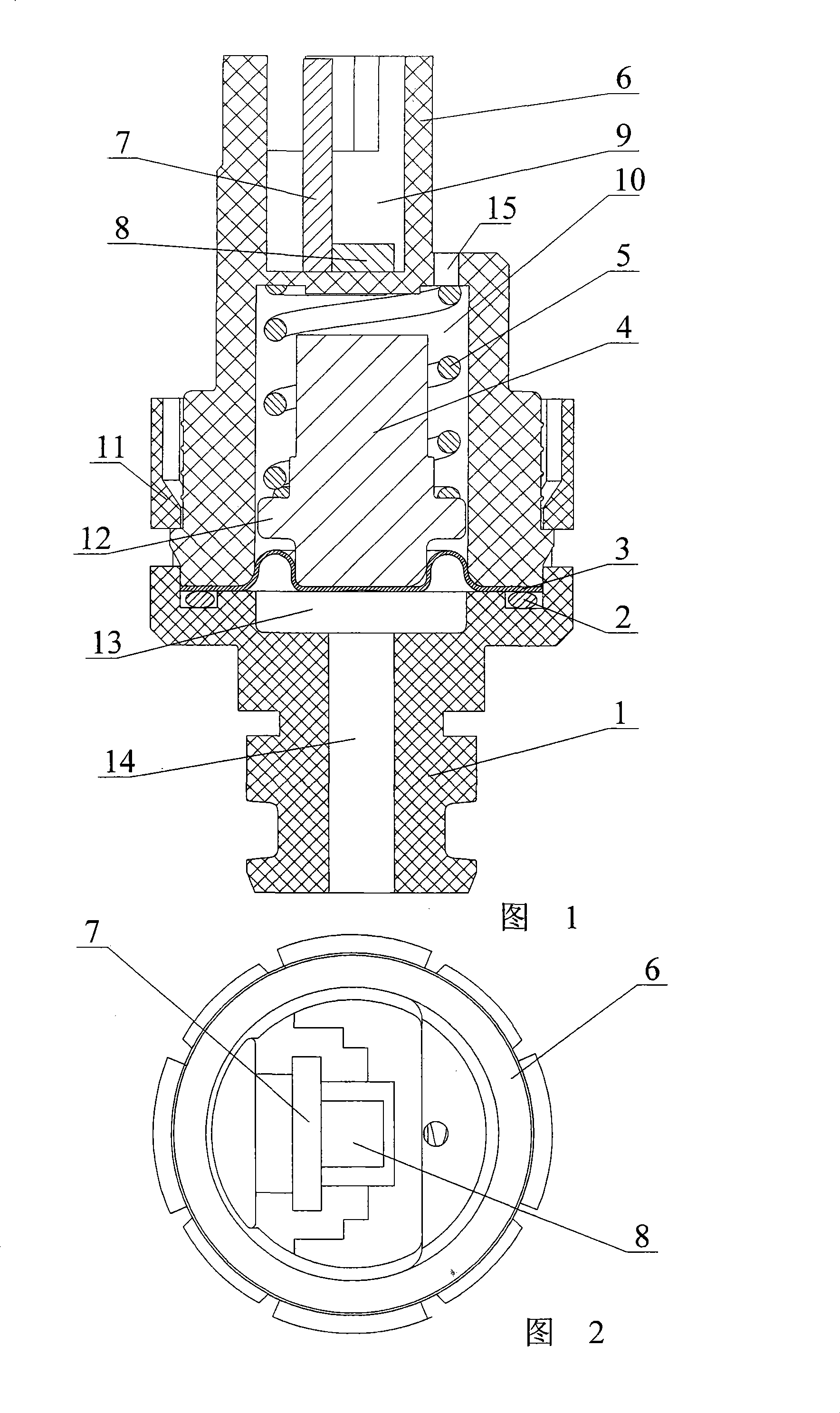
[0011] As shown in the figure: there is a connecting sleeve 6 on the top of the base 1, and a non-magnetic elastic diaphragm 3 is arranged at the junction of the base 1 and the connecting sleeve 6; the upper part of the connecting sleeve 6 is the output cavity 9, and the lower part is Acquisition chamber 10; a linear programmable Hall device 8 is set in the output chamber 9; a magnetic device that can move up and down in the collection chamber 10 is set in the collection chamber 10 under the drive of the non-magnetic elastic diaphragm 3 Steel 4; the lower end of the magnetic steel 4 is in contact with the nonmagnetic elastic diaphragm 3, and the upper part of the magnetic steel 4 is provided with an elastic body for making the lower end surface of the magnetic steel 4 contact the nonmagnetic elastic diaphragm 3. When working, the gas enters the bottom of the non-magnetic elastic diaphragm 3 from the base 1, and presses the non-magnetic elastic diaphragm 3. The non-magnetic elas...


PUM


Abstract

The invention relates to a sensor, in particular to a pressure detection sensor. The pressure detection sensor adopts the technical proposal that a connecting sleeve is arranged on a base. The pressure detection sensor is characterized in that a non-magnetic conductive elastic membrane is arranged on a joint of the base and the connecting sleeve; the upper part of the connecting sleeve is provided with an output cavity and the lower part of the connecting sleeve is provided with a collecting cavity; a linear programmable Hall device is arranged inside the output cavity; a magnetic steel which can be driven by the non-magnetic conductive elastic membrane to move up and down in the collecting cavity is arranged inside the collecting cavity; and the lower end of the magnetic steel contacts the non-magnetic conductive elastic membrane, and the upper part of the magnetic steel is provided with an elastomer which is used for making the lower end face of the magnetic steel contact the non-magnetic conductive elastic membrane. The pressure detection sensor can improve the reliability and the stability of the product.

Description

technical field [0001] The invention relates to a sensor, in particular to a pressure detection sensor. Background technique [0002] The sensor is mainly used for pressure detection of building water supply system, automobile engine oil pressure, automobile brake pressure and industrial automation. Traditional pressure detection devices include silicon piezoresistive pressure sensors, ceramic pressure sensors or capacitive pressure sensors. The common characteristics of these sensors are: relatively complex structure, difficult to process, relatively high requirements for temperature compensation and circuits, resulting in cost Relatively high, usually hundreds to thousands of dollars each. Contents of the invention [0003] The purpose of the present invention is to design a pressure detection sensor to improve the reliability and stability of the product. [0004] According to the technical solution provided by the present invention, there is a connecting sleeve on th...

Claims


Application Information

Patent Timeline
Patent Type & Authority Applications(China)
IPC IPC(8): G01L9/14
Inventor 韩茂良
Owner 江苏晶石科技集团有限公司
Why Eureka
Try Eureka