Split pattern displacement deviation monitoring system

A technology for monitoring system and grating displacement, which is applied in the field of gratings, can solve the problems affecting the spatial characteristics of laser pulses and cannot meet the stability requirements of grating splicing, and achieve the effects of small space, convenient operation and high measurement accuracy

Inactive Publication Date: 2009-04-29
SHANGHAI INST OF OPTICS & FINE MECHANICS CHINESE ACAD OF SCI
View PDF0 Cites 15 Cited by
  • Summary
  • Abstract
  • Description
  • Claims
  • Application Information

AI Technical Summary

Benefits of technology

This technology improves upon existing methods for aligning optical fibers with other components such as connectors or filters used during manufacturing processes by reducing variations caused by factors like temperature changes that can affect alignment quality. It also allows for precise placement within specific areas without adding extra equipment at an increased risk compared to traditional techniques. Overall, this new method provides improved performance over previous methods while being more efficient, accurate, reliable, easy to use, compact, etc., which are important technical benefits.

Problems solved by technology

This patented technology describes how to create very long narrow grille patterns by combining multiple smaller submillers together into larger ones called Ground Spacell Grids. These techniques involve aligning different layers of material at specific locations before adding another layer can improve their alignment precision. Additionally, these methods aim to maintain stable performance over longer periods without causing any instability issues such as thermal expansion caused by temperature changes.

Method used


Image

  • Split pattern displacement deviation monitoring system
  • Split pattern displacement deviation monitoring system
  • Split pattern displacement deviation monitoring system

Examples


Embodiment Construction

[0023] The present invention will be further described below in conjunction with the accompanying drawings and embodiments, but the protection scope of the present invention should not be limited thereby.

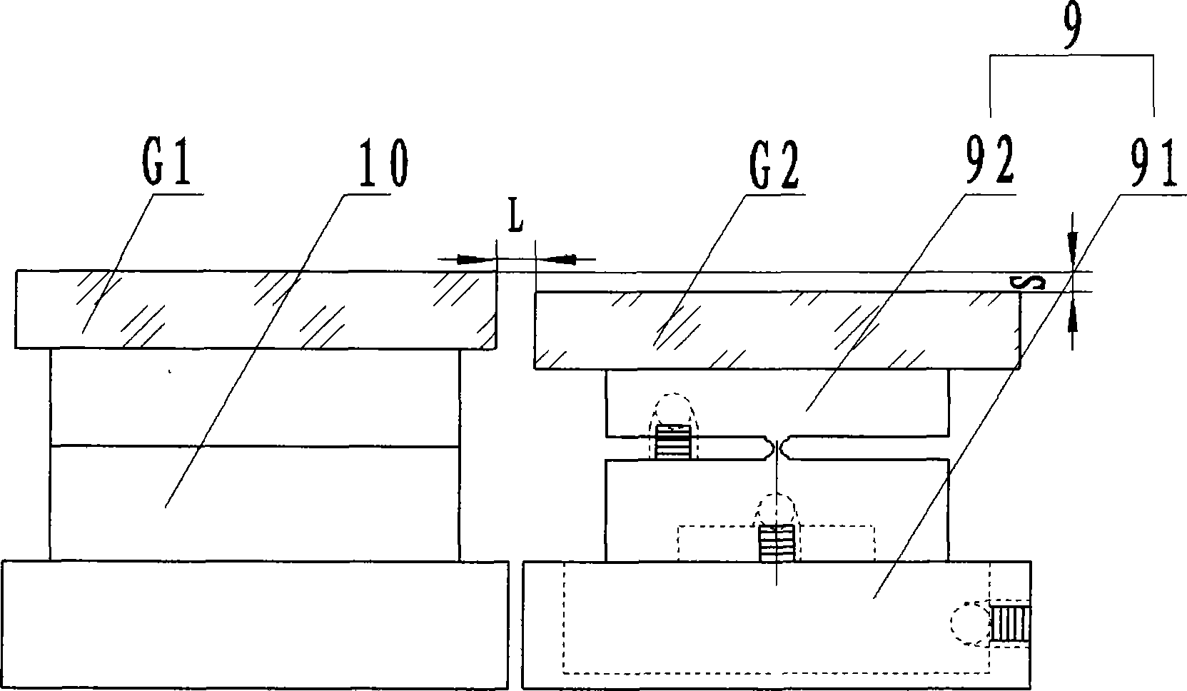
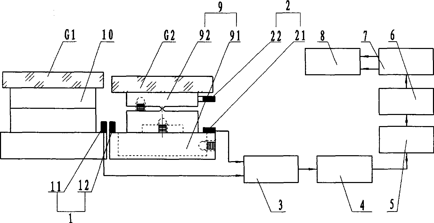
[0024] see figure 2 , figure 2 It is a structural schematic diagram of the spliced ​​grating displacement deviation monitoring system of the present invention. It can be seen from the figure that the spliced ​​grating displacement deviation monitoring system of the present invention includes:

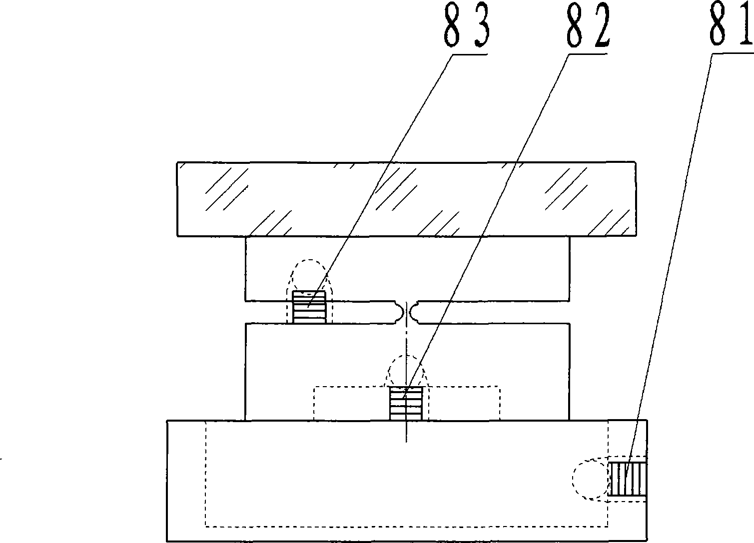
[0025] The adjustment platform is composed of a rough adjustment device platform 10 and a fine adjustment device platform 9, the described coarse adjustment device platform 10 has a locking structure, and the described fine adjustment device platform 9 is composed of a bottom platform 91 and an upper platform 92, the fine adjustment device The platform 9 is equipped with a horizontal piezoelectric ceramic driver 81 and vertical piezoelectric ceramic drivers 82, 83, the piezoelectr...


PUM


Abstract

The invention relates to a tiled grating displacement error monitoring system, which comprises a grating tiling device for mounting a tiled grating, wherein a fine adjuster platform of the grating tiling device is provided with a piezoceramics driver; two polar plates of a first digital capacitance micro-displacement sensor are oppositely arranged on positions in the horizontal direction of a coarse adjuster platform and a lower platform of the fine adjuster respectively; two polar plates of a second digital capacitance micro-displacement sensor are oppositely arranged on positions perpendicular to the lower platform and an upper platform of the fine adjuster respectively; output ends of the first and second digital capacitance micro-displacement sensors are connected with the input end of a signal sample circuit; the output end of the signal sample circuit is connected with the input end of a controller of a singlechip; the output end of the singlechip is connected with a PC through a serial port communication circuit; and the output end of the PC is connected with the control end of the piezoceramics driver through a D/A converter.

Description


Claims


Application Information

Patent Timeline
Owner SHANGHAI INST OF OPTICS & FINE MECHANICS CHINESE ACAD OF SCI
Why Eureka
Try Eureka