
Pressure difference type solar tracking system

A sun tracking and differential pressure technology, applied in the field of sun tracking systems, can solve problems such as the inability to provide power to solar panels

Inactive Publication Date: 2009-04-29
林健峰 +1
View PDF0 Cites 9 Cited by
  • Summary
  • Abstract
  • Description
  • Claims
  • Application Information

AI Technical Summary

Problems solved by technology

[0005] The disadvantage of the above-mentioned traditional solar panel sun tracking system is that the light sensing component only provides the sun offset signal, and cannot provide power to deflect the solar panel to the desired position. This system requires external power to provide the deflection system to drive the solar panel deflection

Method used


Image

  • Pressure difference type solar tracking system
  • Pressure difference type solar tracking system
  • Pressure difference type solar tracking system

Examples


Embodiment Construction

[0017] The present invention will be described in further detail below in conjunction with the accompanying drawings and embodiments.

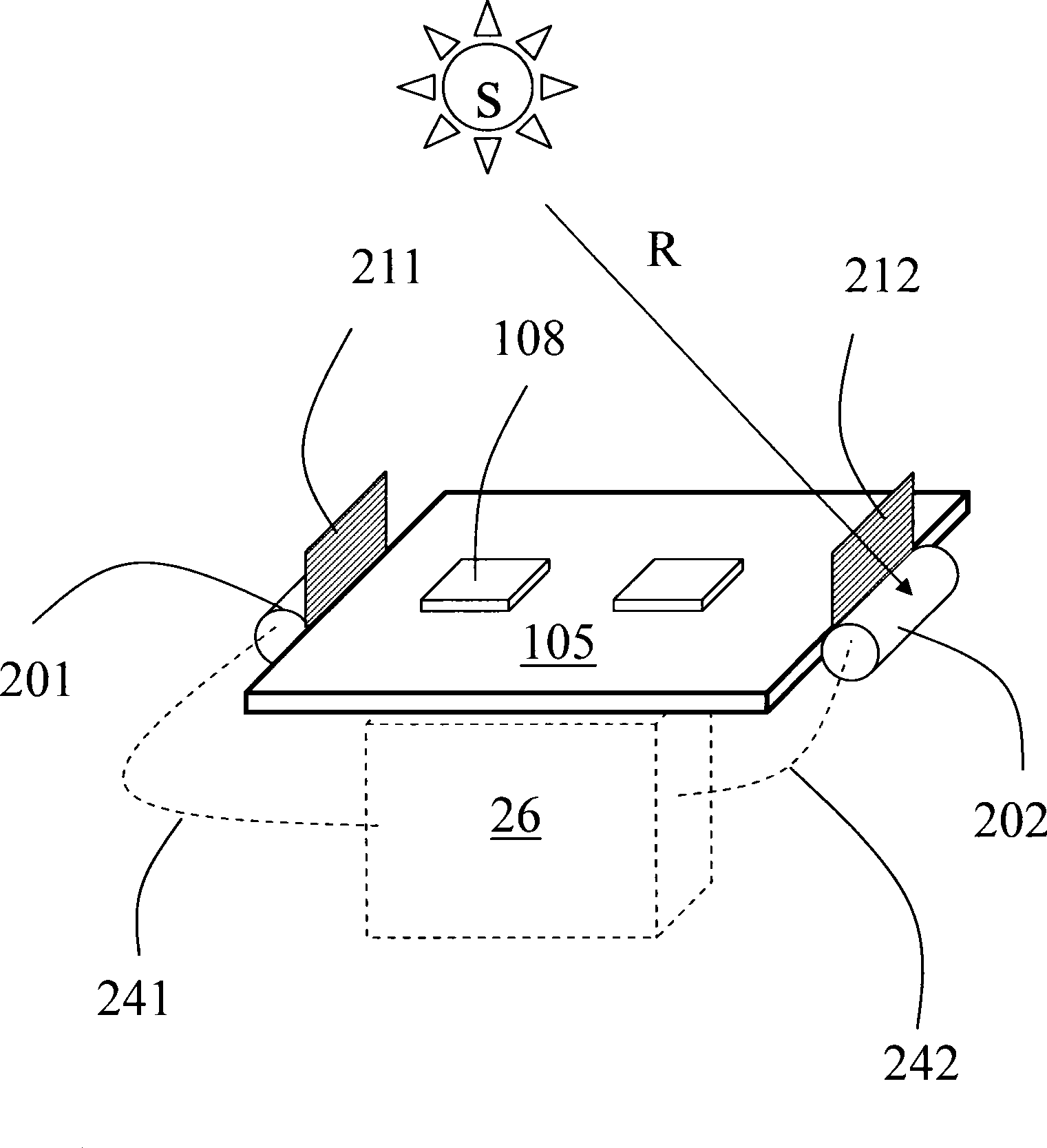
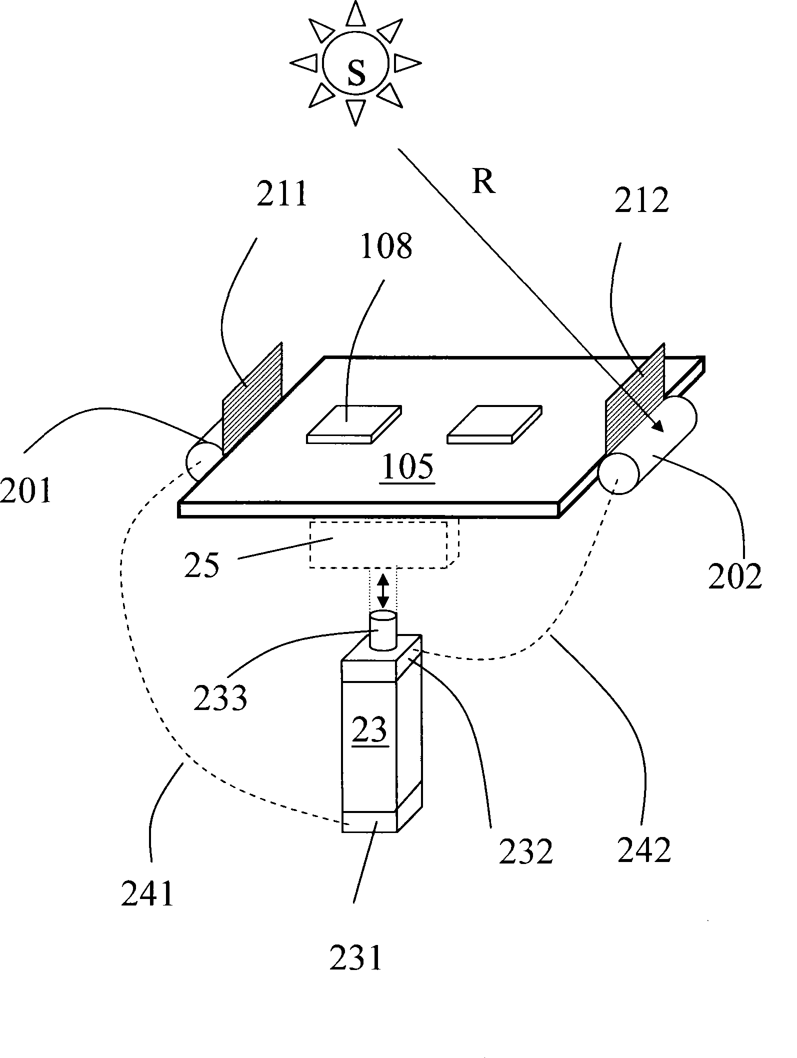
[0018] Such as figure 2 It is a structural schematic diagram of the differential pressure sun tracking system provided by the first preferred embodiment of the present invention. The figure shows a solar substrate 105 with photoelectric components 108 installed; a first refrigerant pressure storage tank 201 is placed on the left, and the first pressure is generated in the tank due to the irradiation of the sun S; a second refrigerant pressure storage tank 202 is placed on the right, The second pressure is generated in the tank due to sunlight; the first baffle 211 is arranged on one side of the first pressure storage tank 201 ; the second baffle 212 is arranged on one side of the second pressure storage tank 202 . When the sun shines directly above, the two pressure storage tanks are heated equally, so the internal pressures of the two press...


PUM


Abstract

The invention relates to a solar panel, in particular to a solar tracking system used for the solar panel. The solar tracking system comprises a substrate, a control unit, a first pressure storage tank and a second pressure storage tank which are arranged in different orientation of the substrate; the first pressure storage tank and the second pressure storage tank respectively generate a first pressure and a second pressure; when the first pressure and the second pressure have a difference, the control unit uses the pressure difference to defect the substrate. The solar tracking system uses the pressure difference generated at tow sides of the refrigerant pressure storage tanks to start an actuating rod so as to adjust the position of the solar panel so that the solar panel deviates to one side of the refrigerant pressure storage tank of large pressure, thus achieving the object of continuously tracking the sunlight.

Description

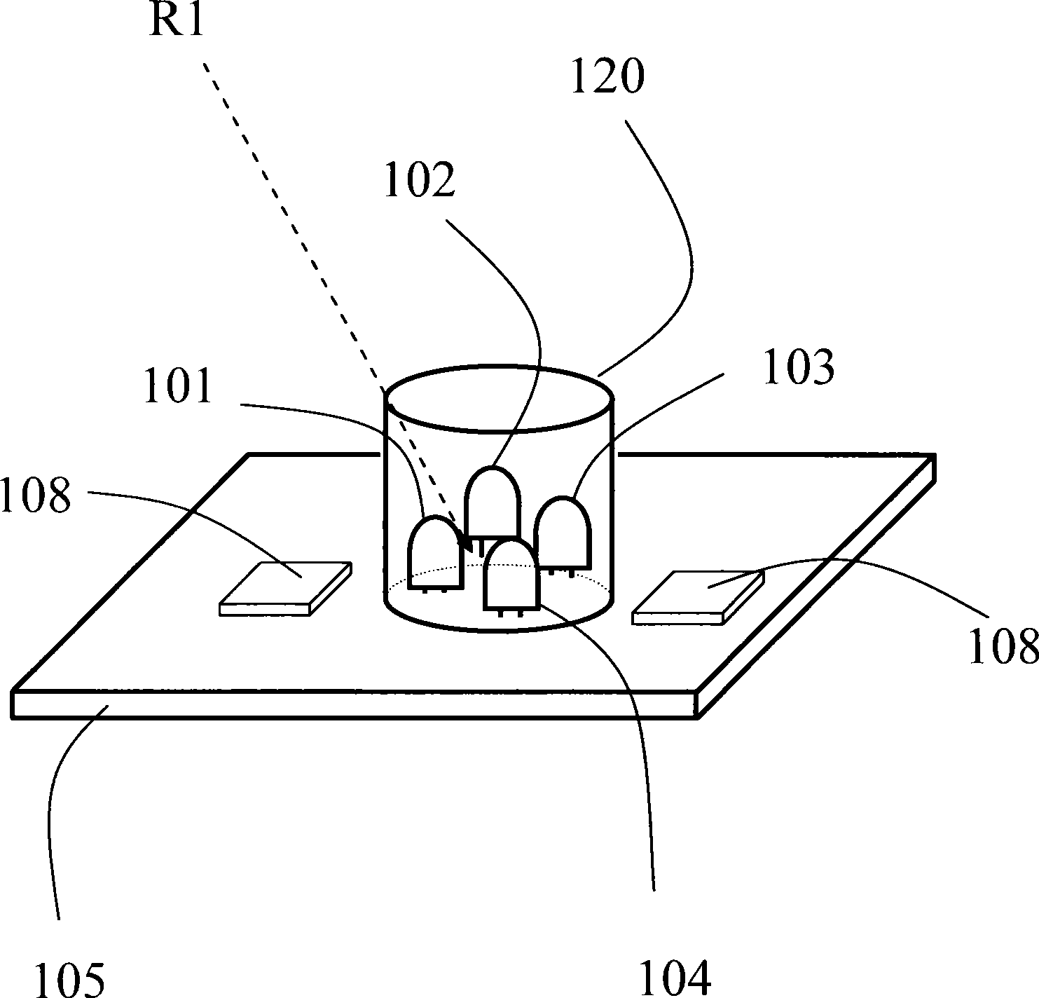
technical field [0001] The present invention relates to a solar panel, in particular to a solar tracking system for a solar panel. Background technique [0002] Such as figure 1 Shown is a solar tracking system of a traditional solar panel, its light sensing unit includes four light sensing components 101, 102, 103 and 104, which are arranged in four directions at the center of the substrate 105, and a sleeve 120 has a The parallel plane 105 is open above, and the cover is around the sensing components 101 , 102 , 103 , and 104 . Sleeve 120 has a side wall of uniform height, constituting a conventional sun tracking system. The photoelectric unit 108 is arranged around the surface of the substrate 105 to receive sunlight energy and then convert the sunlight energy into electrical energy. When the sun hits the traditional sun tracking system directly from above, theoretically, the four light sensing components 101 , 102 , 103 and 104 receive a uniform amount of light. In o...

Claims


Application Information

Patent Timeline
Patent Type & Authority Applications(China)
IPC IPC(8): H02N6/00G05D3/00G05D3/12F24J2/38F24S50/20H02S20/32
CPCY02E10/47Y02E10/50
Inventor 蔡习训郑东升冯慧平
Owner 林健峰
Learn More